Toyota Yaris: Sfi System / Throttle Actuator "A" Control Throttle Body Range/Performance (P211900,P211904,P211977,P21199B)
DESCRIPTION
The electronic throttle control system is composed of the throttle actuator, throttle position sensor, accelerator pedal position sensor, and ECM. The ECM operates the throttle actuator to regulate the throttle valve in response to driver inputs. The throttle position sensor detects the opening angle of the throttle valve, and provides the ECM with feedback so that the throttle valve can be appropriately controlled by the ECM.
| DTC No. | Detection Item | DTC Detection Condition | Trouble Area | MIL | Note |
|---|---|---|---|---|---|
| P211900 | Throttle Actuator "A" Control Throttle Body Range/Performance | The throttle valve opening angle continues to vary greatly from the target opening angle (1 trip detection logic). |
| Comes on | SAE: P2119 |
| P211904 | Throttle Actuator "A" Control Throttle Body Range/Performance System Internal Failure | The throttle valve opening angle continues to vary greatly from the target opening angle (1 trip detection logic). |
| Comes on | SAE: P2119 |
| P211977 | Throttle Actuator "A" Control Throttle Body Range/Performance Commanded Position Not Reachable | The throttle valve opening angle continues to vary greatly from the target opening angle (1 trip detection logic). |
| Comes on | SAE: P2119 |
| P21199B | Throttle Actuator "A" Control Throttle Body High/Excessive Flow | The throttle valve opening angle continues to vary greatly from the target opening angle (1 trip detection logic). |
| Comes on | SAE: P2119 |
MONITOR DESCRIPTION
The ECM determines the actual opening angle of the throttle valve from the throttle position sensor signal. The actual opening angle is compared to the target opening angle commanded by the ECM. If the difference between these two values is outside the standard range, the ECM interprets this as a malfunction in the electronic throttle control system, illuminates the MIL and stores this DTC.
MONITOR STRATEGY
| Required Sensors/Components | Throttle actuator (throttle body with motor assembly) |
| Frequency of Operation | Continuous |
TYPICAL ENABLING CONDITIONS
| System guard* judge condition | On |
| *: System guard is on when the following conditions are met | - |
| Throttle actuator | On |
| Throttle actuator duty calculation | Executing |
| Throttle position sensor malfunction (monitor of following codes judged fail in this trip) | Not detecting |
| Throttle actuator current-cut operation | Not executing |
| Throttle actuator power supply | 4 V or higher |
| Throttle motor malfunction (monitor of following code judged fail in this trip) | Not detecting |
TYPICAL MALFUNCTION THRESHOLDS
| Either of the following conditions is met | 1 or 2 |
| 1. Difference between commanded closed throttle position and current closed throttle position | 0.3 V or higher |
| 2. Difference between commanded open throttle position and current open throttle position | 0.3 V or higher |
CONFIRMATION DRIVING PATTERN
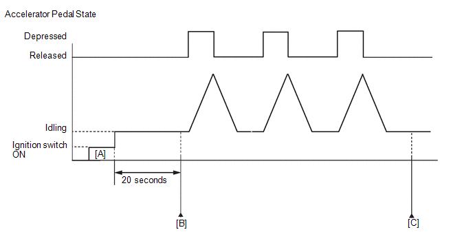
- Connect the GTS to the DLC3.
- Turn the ignition switch to ON.
- Turn the GTS on.
- Clear the DTCs (even if no DTCs are stored, perform the clear DTC procedure).
- Turn the ignition switch off and wait for at least 30 seconds.
- Turn the ignition switch to ON [A].
- Turn the GTS on.
- Start the engine.
- Idle the engine for 20 seconds.
- Enter the following menus: Powertrain / Engine / Trouble Codes [B].
-
Read the pending DTCs.
HINT:
- If a pending DTC is output, the system is malfunctioning.
- If a pending DTC is not output, perform the following procedure.
- Enter the following menus: Powertrain / Engine / Utility / All Readiness.
- Input the DTC: P211900, P211904, P211977 or P21199B.
-
Check the DTC judgment result.
GTS Display
Description
NORMAL
- DTC judgment completed
- System normal
ABNORMAL
- DTC judgment completed
- System abnormal
INCOMPLETE
- DTC judgment not completed
- Perform driving pattern after confirming DTC enabling conditions
HINT:
- If the judgment result is NORMAL, the system is normal.
- If the judgment result is ABNORMAL, the system is malfunctioning.
- If the judgment result is INCOMPLETE, fully depress and release the accelerator pedal 3 times, and then check the DTC judgment result [C].
FAIL-SAFE
When any of these DTCs are stored, the ECM enters fail-safe mode. During fail-safe mode, the ECM cuts the current to the throttle actuator, and the throttle valve is returned to a 8° throttle valve opening angle by the return spring. The ECM then adjusts the engine output by controlling the fuel injection (intermittent fuel-cut) and ignition timing, in accordance with the accelerator pedal opening angle, to allow the vehicle to continue running at a minimal speed. If the accelerator pedal is depressed firmly and gently, the vehicle can be driven slowly.
Fail-safe mode continues until a pass condition is detected, and the ignition switch is then turned off.
WIRING DIAGRAM
Refer to DTC P210018.
Click here

CAUTION / NOTICE / HINT
HINT:
-
Refer to "Data List / Active Test" [Throttle Position Sensor No.1 Voltage, Throttle Position Sensor No.2 Voltage, Throttle2 Throttle Position Sensor No.1 Voltage, Throttle2 Throttle Position Sensor No.2 Voltage, Throttle Position Command, Throttle2 Throttle Position Command, Throttle Motor Current, Throttle2 Throttle Motor Current, Throttle Motor Duty Ratio (Open), Throttle Motor Duty Ratio (Close), Throttle2 Throttle Motor Duty Ratio (Open) and Throttle2 Throttle Motor Duty Ratio (Close)].
Click here

- Read Freeze Frame Data using the GTS. The ECM records vehicle and driving condition information as Freeze Frame Data the moment a DTC is stored. When troubleshooting, Freeze Frame Data can help determine if the vehicle was moving or stationary, if the engine was warmed up or not, if the air fuel ratio was lean or rich, and other data from the time the malfunction occurred.
PROCEDURE
| 1. | CHECK ANY OTHER DTCS OUTPUT (IN ADDITION TO DTC P211900, P211904, P211977 OR P21199B) |
(a) Read the DTCs.
Powertrain > Engine > Trouble Codes| Result | Proceed to |
|---|---|
| P211900, P211904, P211977 or P21199B is output | A |
| P211900, P211904, P211977 or P21199B and other DTCs are output | B |
HINT:
If any DTCs other than P211900, P211904, P211977 or P21199B are output, troubleshoot those DTCs first.
| B |
 | GO TO DTC CHART |
|

| 2. | CLEAR DTC |
(a) Clear the DTCs.
Powertrain > Engine > Clear DTCs(b) Turn the ignition switch off and wait for at least 30 seconds.
|

| 3. | READ VALUE USING GTS (THROTTLE POSITION) |
(a) Start the engine.
(b) Enter the following menus.
Powertrain > Engine > Data List| Tester Display |
|---|
| Throttle Position Sensor No.1 Voltage |
| Throttle Position Command |
(c) Read the values displayed on the GTS while fully depressing and releasing the accelerator pedal quickly.
| Result | Proceed to |
|---|---|
| Throttle Position Sensor No.1 Voltage does not change | A |
| Throttle Position Sensor No.1 Voltage changes even a little | B |
HINT:
When a DTC is output, the system changes to fail-safe mode. Therefore, only use the data up until the time the DTC is stored for confirmation.
| B |
 | GO TO STEP 5 |
|

| 4. | INSPECT THROTTLE BODY WITH MOTOR ASSEMBLY (RESISTANCE OF THROTTLE ACTUATOR) |
Click here

| NG |
 | GO TO STEP 9 |
|

| 5. | INSPECT THROTTLE BODY WITH MOTOR ASSEMBLY (VISUALLY CHECK THROTTLE VALVE) |
(a) Check for foreign matter between the throttle valve and housing. If necessary, clean the throttle body with motor assembly. Also, check that the throttle valve moves smoothly.
OK:
Throttle valve is not contaminated with foreign matter and moves smoothly.
HINT:
-
When cleaning or replacing one throttle body with motor assembly, clean the other throttle body with motor assembly.
Click here

-
Perform "Inspection After Repair" after cleaning the throttle body with motor assembly.
Click here

| NG |
 | GO TO STEP 9 |
|

| 6. | CLEAR DTC |
(a) Clear the DTCs.
Powertrain > Engine > Clear DTCs(b) Turn the ignition switch off and wait for at least 30 seconds.
|

| 7. | READ VALUE USING GTS (THROTTLE POSITION) |
(a) Enter the following menus.
Powertrain > Engine > Data List| Tester Display |
|---|
| Throttle Position Sensor No.1 Voltage |
| Throttle Position Sensor No.2 Voltage |
| Throttle Position Command |
(b) Read the values displayed on the GTS while wiggling the ECM wire harness.
(c) Read the DTCs.
Powertrain > Engine > Trouble Codes| Result | Proceed to |
|---|---|
| Value in Data List changes when wire harness is wiggled, or DTC is output | A |
| Other than above | B |
| B |
 | GO TO STEP 10 |
|

| 8. | REPAIR OR REPLACE HARNESS OR CONNECTOR (THROTTLE BODY WITH MOTOR ASSEMBLY - ECM) |
(a) As the DTC was stored due to a change in the contact resistance of the connector, repair or replace the wire harness or connector.
Click here

| NEXT |
 | END |
| 9. | REPLACE THROTTLE BODY WITH MOTOR ASSEMBLY |
Click here

HINT:
-
When cleaning or replacing one throttle body with motor assembly, clean the other throttle body with motor assembly.
Click here

-
Perform "Inspection After Repair" after replacing the throttle body with motor assembly.
Click here

|

| 10. | CLEAR DTC |
(a) Clear the DTCs.
Powertrain > Engine > Clear DTCs(b) Turn the ignition switch off and wait for at least 30 seconds.
|

| 11. | CHECK WHETHER DTC OUTPUT RECURS (DTC P211900, P211904, P211977 or P21199B) |
(a) Drive the vehicle in accordance with the driving pattern described in Confirmation Driving Pattern.
(b) Read the DTCs.
Powertrain > Engine > Trouble Codes| Result | Proceed to |
|---|---|
| DTCs are not output | A |
| P211900, P211904, P211977 or P21199B is output | B |
| A |
 | END |
| B |
 | REPLACE ECM |
 Throttle Actuator "A" Control System Actuator Stuck Open (P211172,P211173)
DESCRIPTION The throttle actuator is operated by the ECM, and opens and closes the throttle valve using gears. The opening angle of the throttle valve is detected by the throttle position sensor, which is mounted on the throttle body with motor assembly...
 Throttle/Pedal Position Sensor/Switch "D" Circuit Short to Battery (P212012,P212014,P21201C,P21201F,P212099,P212512,P212514,P21251F,P21382B)
DESCRIPTION HINT: These DTCs relate to the accelerator pedal position sensor. The accelerator pedal position sensor is built into the accelerator pedal sensor assembly and has 2 sensor circuits: VPA (main) and VPA2 (sub)...
Other information:
Toyota Yaris XP210 (2020-2025) Owner's Manual: Cleaning the Lap/Shoulder Belt Webbing
Clean the webbing with a mild soap solution recommended for upholstery or carpets. Follow instructions. Do not bleach or dye the webbing; this may weaken it. After cleaning the belts, thoroughly dry the belt webbing and make sure there is no remaining moisture before retracting them...
Toyota Yaris XP210 (2020-2025) Reapir and Service Manual: Removal
REMOVAL CAUTION / NOTICE / HINT The necessary procedures (adjustment, calibration, initialization, or registration) that must be performed after parts are removed, installed, or replaced during the air fuel ratio sensor removal/installation are shown below...
Categories
- Manuals Home
- Toyota Yaris Owners Manual
- Toyota Yaris Service Manual
- Engine & Hybrid System
- How to use USB mode
- To Set Speed
- New on site
- Most important about car
Front Seat Belt Pretensioners
The front seat belt pretensioners are designed to deploy in moderate or severe frontal, near frontal collisions.
In addition, the pretensioners operate when a side collision or a rollover accident is detected. The pretensioners operate differently depending on what types of air bags are equipped. For more details about the seat belt pretensioner operation, refer to the SRS Air Bag Deployment Criteria.