Toyota Yaris: Sfi System / Throttle/Pedal Position Sensor/Switch "D" Circuit Short to Battery (P212012,P212014,P21201C,P21201F,P212099,P212512,P212514,P21251F,P21382B)
DESCRIPTION
HINT:
These DTCs relate to the accelerator pedal position sensor.
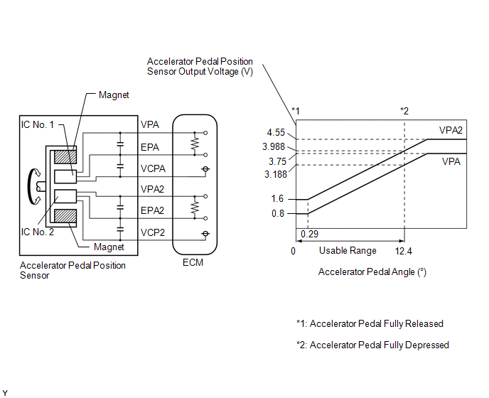
The accelerator pedal position sensor is built into the accelerator pedal sensor assembly and has 2 sensor circuits: VPA (main) and VPA2 (sub). This sensor is a non-contact type sensor and uses Hall-effect elements in order to yield accurate signals even in extreme driving conditions, such as at high speeds as well as very low speeds. The voltage, which is applied to terminals VPA and VPA2 of the ECM, varies between 0.5 V and 4.75 V in proportion to the operating angle of the accelerator pedal (throttle valve). A signal from VPA indicates the actual accelerator pedal opening angle (throttle valve opening angle) and is used for engine control. A signal from VPA2 conveys the status of the VPA circuit and is used to check the accelerator pedal position sensor itself.
The ECM monitors the actual accelerator pedal opening angle (throttle valve opening angle) through the signals from VPA and VPA2, and controls the throttle actuator according to these signals.
| DTC No. | Detection Item | DTC Detection Condition | Trouble Area | MIL | Note |
|---|---|---|---|---|---|
| P212012 | Throttle/Pedal Position Sensor/Switch "D" Circuit Short to Battery | VPA is 4.8 V or higher for 2 seconds or more (1 trip detection logic). |
| Comes on | SAE: P2123 |
| P212014 | Throttle/Pedal Position Sensor/Switch "D" Circuit Short to Ground or Open | VPA is 0.4 V or less for 0.5 seconds or more when the accelerator pedal is depressed (1 trip detection logic). |
| Comes on | SAE: P2122 |
| P21201C | Throttle/Pedal Position Sensor/Switch "D" Circuit Voltage Out of Range | Difference between VPA and VPA2 is greater than or equal to the specified value for 0.5 seconds (1 trip detection logic). |
| Comes on | SAE: P2121 |
| P21201F | Throttle/Pedal Position Sensor/Switch "D" Circuit Intermittent | VPA fluctuates rapidly beyond the upper and lower malfunction thresholds for 0.5 seconds or more (1 trip detection logic). |
| Comes on | SAE: P2120 |
| P212099 | Throttle/Pedal Position Sensor/Switch "D" Exceeded Learning Limit | Difference between VPA and VPA2 is less than 0.4 V, or higher than 1.2 V (learned value of accelerator off position) (1 trip detection logic). |
| Comes on | SAE: P2121 |
| P212512 | Throttle/Pedal Position Sensor/Switch "E" Circuit Short to Battery | Both of the following conditions are met for 2 seconds or more (1 trip detection logic): (a) VPA2 is 4.8 V or higher. (b) VPA is between 0.4 V and 3.45 V. |
| Comes on | SAE: P2128 |
| P212514 | Throttle/Pedal Position Sensor/Switch "E" Circuit Short to Ground or Open | VPA2 is 1.2 V or less for 0.5 seconds or more when the accelerator pedal is depressed (1 trip detection logic). |
| Comes on | SAE: P2127 |
| P21251F | Throttle/Pedal Position Sensor/Switch "E" Circuit Intermittent | VPA2 fluctuates rapidly beyond the upper and lower malfunction thresholds for 0.5 seconds or more (1 trip detection logic). |
| Comes on | SAE: P2125 |
| P21382B | Throttle/Pedal Position Sensor/Switch "D"/"E" Voltage Correlation Signal Cross Coupled | Difference between VPA and VPA2 is 0.02 V or less for 2.0 seconds or more (1 trip detection logic): |
| Comes on | SAE: P2138 |
HINT:
When any of these DTCs are output, check the accelerator pedal position sensor voltage using the GTS. Enter the following menus: Powertrain / Engine / Data List / Accelerator Position Sensor No.1 Voltage and Accelerator Position Sensor No.2 Voltage.
| Trouble Area | Accelerator Pedal Fully Released | Accelerator Pedal Fully Depressed | ||
|---|---|---|---|---|
| Accelerator Position Sensor No.1 Voltage | Accelerator Position Sensor No.2 Voltage | Accelerator Position Sensor No.1 Voltage | Accelerator Position Sensor No.2 Voltage | |
| Open in VCPA circuit | 0 to 0.2 V | 0 to 0.2 V | 0 to 0.2 V | 0 to 0.2 V |
| Open or ground short in VPA circuit | 0 to 0.2 V | 1.2 to 2.0 V | 0 to 0.2 V | 3.4 to 4.75 V |
| Open or ground short in VPA2 circuit | 0.5 to 1.1 V | 0 to 0.2 V | 2.6 to 4.5 V | 0 to 0.2 V |
| Open in EPA circuit | 4.5 to 4.98 V | 4.5 to 4.98 V | 4.5 to 4.98 V | 4.5 to 4.98 V |
| Normal condition | 0.5 to 1.1 V | 1.2 to 2.0 V | 2.6 to 4.5 V | 3.4 to 4.75 V |
HINT:
Accelerator pedal positions are expressed as voltages.
MONITOR DESCRIPTION
When either output voltage of VPA or VPA2 deviates from the standard range, or the difference between the output voltages of the 2 sensor circuits exceeds the upper or lower threshold, the ECM determines that there is a malfunction in the accelerator pedal position sensor. The ECM then illuminates the MIL and stores a DTC.
Example:
When the output voltage of VPA is 0.4 V or less for 0.5 seconds or more when the accelerator pedal is fully depressed, DTC P212014 is stored.
MONITOR STRATEGY
| Required Sensors/Components | Accelerator pedal sensor assembly |
| Frequency of Operation | Continuous |
CONFIRMATION DRIVING PATTERN
P212012, P212014, P21201F, P212512, P212514, P21251F and P21382B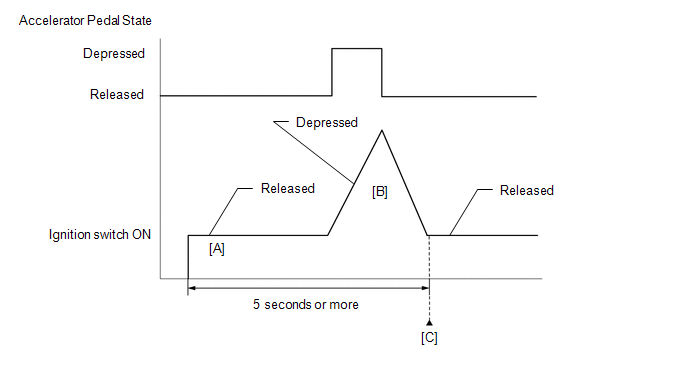
- Connect the GTS to the DLC3.
- Turn the ignition switch to ON.
- Turn the GTS on.
- Clear the DTCs (even if no DTCs are stored, perform the clear DTC procedure).
- Turn the ignition switch off and wait for at least 30 seconds.
- Turn the ignition switch to ON [A].
- Turn the GTS on.
- Fully depress and release the accelerator pedal [B].
- Check that 5 seconds or more have elapsed since the ignition switch to ON.
- Enter the following menus: Powertrain / Engine / Trouble Codes [C].
-
Read the pending DTCs.
HINT:
- If a pending DTC is output, the system is malfunctioning.
- If a pending DTC is not output, perform the following procedure.
- Enter the following menus: Powertrain / Engine / Utility / All Readiness.
- Input the DTC: P212012, P212014, P21201F, P212512, P212514, P21251F or P21382B.
-
Check the DTC judgment result.
GTS Display
Description
NORMAL
- DTC judgment completed
- System normal
ABNORMAL
- DTC judgment completed
- System abnormal
INCOMPLETE
- DTC judgment not completed
- Perform driving pattern after confirming DTC enabling conditions
HINT:
- If the judgment result is NORMAL, the system is normal.
- If the judgment result is ABNORMAL, the system is malfunctioning.
- If the judgment result is INCOMPLETE, perform steps [B] through [C] again.
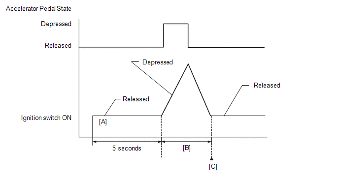
- Connect the GTS to the DLC3.
- Turn the ignition switch to ON.
- Turn the GTS on.
- Clear the DTCs (even if no DTCs are stored, perform the clear DTC procedure).
- Turn the ignition switch off and wait for at least 30 seconds.
- Turn the ignition switch to ON [A].
- Turn the GTS on.
- Wait for 5 seconds after turning the ignition switch to ON.
-
Operate the accelerator pedal in accordance with the following procedure [B].
- Enter the following menus: Powertrain / Engine / Data List / Accelerator Position Sensor No.1 Voltage % and Accelerator Position Sensor No.2 Voltage %.
- Slowly depress the accelerator pedal until Accelerator Position Sensor No.1 Voltage % is approximately 30% and Accelerator Position Sensor No.2 Voltage % is approximately 46%, then slowly release the accelerator pedal.
- Enter the following menus: Powertrain / Engine / Trouble Codes [C].
-
Read the pending DTCs.
HINT:
- If a pending DTC is output, the system is malfunctioning.
- If a pending DTC is not output, perform the following procedure.
- Enter the following menus: Powertrain / Engine / Utility / All Readiness.
- Input the DTC: P21201C or P212099.
-
Check the DTC judgment result.
GTS Display
Description
NORMAL
- DTC judgment completed
- System normal
ABNORMAL
- DTC judgment completed
- System abnormal
INCOMPLETE
- DTC judgment not completed
- Perform driving pattern after confirming DTC enabling conditions
HINT:
- If the judgment result is NORMAL, the system is normal.
- If the judgment result is ABNORMAL, the system is malfunctioning.
- If the judgment result is INCOMPLETE, perform steps [B] through [C] again.
FAIL-SAFE
When these DTCs are stored, the ECM enters fail-safe mode. If either of the 2 sensor circuits malfunctions, the ECM limits the engine output. If both of the circuits malfunction, the ECM regards the accelerator pedal as being released. As a result, the throttle valve is closed and the engine idles.
Fail-safe mode continues until a pass condition is detected, and the ignition switch is turned off.
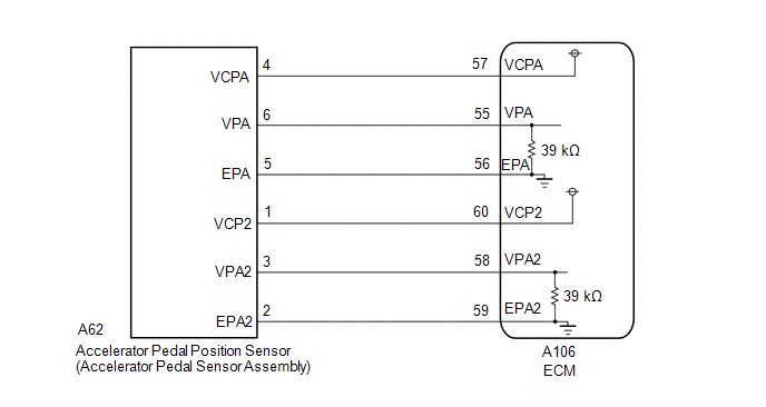
WIRING DIAGRAM
CAUTION / NOTICE / HINT
HINT:
Read Freeze Frame Data using the GTS. The ECM records vehicle and driving condition information as Freeze Frame Data the moment a DTC is stored. When troubleshooting, Freeze Frame Data can help determine if the vehicle was moving or stationary, if the engine was warmed up or not, if the air fuel ratio was lean or rich, and other data from the time the malfunction occurred.
PROCEDURE
| 1. | READ VALUE USING GTS (ACCELERATOR PEDAL POSITION SENSOR) |
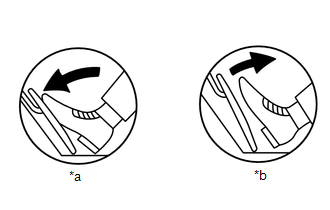
| *a | Fully Depressed |
| *b | Fully Released |
(a) Enter the following menus.
Powertrain > Engine > Data List| Tester Display |
|---|
| Accelerator Position Sensor No.1 Voltage |
| Accelerator Position Sensor No.2 Voltage |
(b) Read the value displayed on the GTS.
Standard Voltage:
| Accelerator Pedal Operation | Accelerator Position Sensor No.1 Voltage | Accelerator Position Sensor No.2 Voltage | Difference between Accelerator Position Sensor No.1 Voltage and Accelerator Position Sensor No.2 Voltage |
|---|---|---|---|
| Fully Released | 0.5 to 1.1 V | 1.2 to 2.0 V | More than 0.02 V |
| Fully Depressed | 2.6 to 4.5 V | 3.4 to 4.75 V |
| OK |
 | CHECK FOR INTERMITTENT PROBLEMS |
|

| 2. | CHECK HARNESS AND CONNECTOR |
HINT:
Make sure that the connector is properly connected. If it is not, securely connect it and check for DTCs again.
(a) Disconnect the accelerator pedal sensor assembly connector.
(b) Turn the ignition switch to ON.
| (c) Measure the voltage according to the value(s) in the table below. Standard Voltage:
|
|
(d) Turn the ignition switch off and wait for at least 30 seconds.
(e) Measure the resistance according to the value(s) in the table below.
Standard Resistance:
| Tester Connection | Condition | Specified Condition |
|---|---|---|
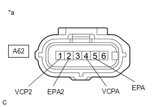
| A62-6(VPA) - A62-5(EPA) | Ignition switch off | 36.60 to 41.61 kΩ |
| A62-3(VPA2) - A62-2(EPA2) | Ignition switch off | 36.60 to 41.61 kΩ |
| OK |
 | REPLACE ACCELERATOR PEDAL SENSOR ASSEMBLY |
|

| 3. | CHECK HARNESS AND CONNECTOR (ACCELERATOR PEDAL SENSOR ASSEMBLY - ECM) |
(a) Disconnect the accelerator pedal sensor assembly connector.
(b) Disconnect the ECM connector.
(c) Measure the resistance according to the value(s) in the table below.
Standard Resistance:
| Tester Connection | Condition | Specified Condition |
|---|---|---|
| A62-6 (VPA) - A106-55 (VPA) | Always | Below 1 Ω |
| A62-5 (EPA) - A106-56 (EPA) | Always | Below 1 Ω |
| A62-4 (VCPA) - A106-57 (VCPA) | Always | Below 1 Ω |
| A62-3 (VPA2) - A106-58 (VPA2) | Always | Below 1 Ω |
| A62-2 (EPA2) - A106-59 (EPA2) | Always | Below 1 Ω |
| A62-1 (VCP2) - A106-60 (VCP2) | Always | Below 1 Ω |
| A62-6 (VPA) or A106-55 (VPA) - Body ground and other terminals | Always | 10 kΩ or higher |
| A62-5 (EPA) or A106-56 (EPA) - Body ground and other terminals | Always | 10 kΩ or higher |
| A62-4 (VCPA) or A106-57 (VCPA) - Body ground and other terminals | Always | 10 kΩ or higher |
| A62-3 (VPA2) or A106-58 (VPA2) - Body ground and other terminals | Always | 10 kΩ or higher |
| A62-2 (EPA2) or A106-59 (EPA2) - Body ground and other terminals | Always | 10 kΩ or higher |
| A62-1 (VCP2) or A106-60 (VCP2) - Body ground and other terminals | Always | 10 kΩ or higher |
| OK |
 | REPLACE ECM |
| NG |
 | REPAIR OR REPLACE HARNESS OR CONNECTOR |
 Throttle Actuator "A" Control Throttle Body Range/Performance (P211900,P211904,P211977,P21199B)
DESCRIPTION The electronic throttle control system is composed of the throttle actuator, throttle position sensor, accelerator pedal position sensor, and ECM...
 Throttle/Pedal Position Sensor/Switch "A"/"B" Voltage Correlation Signal Cross Coupled (P21352B)
DESCRIPTION Refer to DTC P012011. Click here
DTC No. Detection Item DTC Detection Condition Trouble Area MIL Note P21352B Throttle/Pedal Position Sensor/Switch "A"/"B" Voltage Correlation Signal Cross Coupled The difference between the output voltage of VTA1 and VTA2 is 0...
Other information:
Toyota Yaris XP210 (2020-2025) Reapir and Service Manual: Terminals Of Ecu
TERMINALS OF ECU CHECK POWER DISTRIBUTION BOX ASSEMBLY AND MAIN BODY ECU (MULTIPLEX NETWORK BODY ECU) *1 Power Distribution Box Assembly *2 Main Body ECU (Multiplex Network Body ECU) (a) Remove the main body ECU (multiplex network body ECU) from the power distribution box assembly...
Toyota Yaris XP210 (2020-2025) Reapir and Service Manual: Removal
REMOVAL CAUTION / NOTICE / HINT The necessary procedures (adjustment, calibration, initialization or registration) that must be performed after parts are removed and installed, or replaced during fuel injector assembly removal/installation are shown below...
Categories
- Manuals Home
- Toyota Yaris Owners Manual
- Toyota Yaris Service Manual
- To Set Speed
- Headlights
- Opening and Closing the Liftgate/Trunk Lid
- New on site
- Most important about car
Keys

To use the auxiliary key, press the knob and pull out the auxiliary key from the smart key.
