Toyota Yaris: Power Door Lock Control System / Terminals Of Ecu
TERMINALS OF ECU
CHECK POWER DISTRIBUTION BOX ASSEMBLY AND MAIN BODY ECU (MULTIPLEX NETWORK BODY ECU)
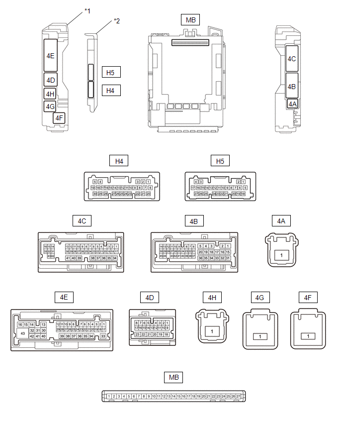
| *1 | Power Distribution Box Assembly | *2 | Main Body ECU (Multiplex Network Body ECU) |
(a) Remove the main body ECU (multiplex network body ECU) from the power distribution box assembly.
Click here

(b) Reconnect the power distribution box assembly connectors.
(c) Measure the voltage and resistance according to the value(s) in the table below.
HINT:
Measure the values on the wire harness side with the connectors connected.
| Terminal No. (Symbol) | Terminal Description | Condition | Specified Condition |
|---|---|---|---|
| MB-13 (GND1) - Body ground | Ground | Always | Below 1 Ω |
| MB-14 (GND2) - Body ground | Ground | Always | Below 1 Ω |
| MB-26 (BECU) - Body ground | Auxiliary battery power supply | Always | 11 to 14 V |
| MB-27 (IGR) - Body ground | IG power supply | Ignition switch ON | 11 to 14 V |
(d) Install the main body ECU (multiplex network body ECU) to the power distribution box assembly.
Click here

(e) Measure the voltage and check for pulses according to the value(s) in the table below.
| Terminal No. (Symbol) | Terminal Description | Condition | Specified Condition |
|---|---|---|---|
| 4E-5 (FRCY) - Body ground | Front door courtesy light switch (for RH) input | Front door RH open | Below 1 V |
| Front door RH closed | 11 to 14 V | ||
| 4E-3 (FLCY) - Body ground | Front door courtesy light switch (for LH) input | Front door LH open | Below 1 V |
| Front door LH closed | 11 to 14 V | ||
| 4E-2 (BCTY) - Body ground | Back door courtesy light switch input | Back door closed | Below 1 V |
| Back door open | 11 to 14 V | ||
| 4E-39 (TR+) - Body ground | Back door lock motor drive output | Back door closed → open | Below 1 V → 11 to 14 V → Below 1 V |
| 4C-36 (ACT-) - Body ground | Door lock motor unlock drive output | Door control switch or driver door key cylinder off → on (unlock) | Below 1 V → 11 to 14 V → Below 1 V |
| 4B-34 (ACT+) - Body ground | Door lock motor lock drive output | Door control switch or driver door key cylinder off → on (lock) | Below 1 V → 11 to 14 V → Below 1 V |
| 4B-19 (ACT+) - Body ground | |||
| H4-3 (LSFR) - Body ground | Front door RH unlock detection switch input | Front door RH unlocked | Below 1 V |
| Front door RH locked | Pulse generation | ||
| H4-9 (LSFL) - Body ground | Front door LH unlock detection switch input | Front door LH unlocked | Below 1 V |
| Front door LH locked | Pulse generation | ||
| H4-28 (L2) - Body ground | Driver door key-linked lock input | Driver door key cylinder turned to lock | Below 1 V |
| H4-28 (L2) - Body ground | Driver door key-linked lock input | Driver door key cylinder not turned | Pulse generation |
| H4-4 (UL3) - Body ground | Driver door key-linked unlock input | Driver door key cylinder turned to unlock | Below 1 V |
| H4-4 (UL3) - Body ground | Driver door key-linked unlock input | Driver door key cylinder not turned | Pulse generation |
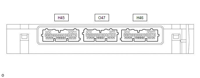
CHECK CERTIFICATION ECU (SMART KEY ECU ASSEMBLY)
(a) Disconnect the H46 certification ECU (smart key ECU assembly) connector.
(b) Measure the voltage and resistance according to the value(s) in the table below.
| Terminal No. (Symbol) | Terminal Description | Condition | Specified Condition |
|---|---|---|---|
| H46-6 (+B) - Body ground | Ground | Always | Below 1 Ω |
| H46-29 (E) - Body ground | Auxiliary battery power supply | Always | 11 to 14 V |
(c) Reconnect the O47 certification ECU (smart key ECU assembly) connector.
(d) Measure the voltage and check for pulses according to the value(s) in the table below.
| Tester Connection | Terminal Description | Condition | Specified Condition |
|---|---|---|---|
| O47-16 (TSW5) - Body ground | Back door opener switch input | Back door opener switch assembly (open switch) off → on | Below 1 V → Pulse generation |
 Problem Symptoms Table
PROBLEM SYMPTOMS TABLE NOTICE: If the main body ECU (multiplex network body ECU) is replaced, refer to the Registration. Click here
HINT:
Use the table below to help determine the cause of problem symptoms...
 Data List / Active Test
DATA LIST / ACTIVE TEST DATA LIST HINT: Using the GTS to read the Data List allows the values or states of switches, sensors, actuators and other items to be read without removing any parts...
Other information:
Toyota Yaris XP210 (2020-2026) Reapir and Service Manual: Inspection
INSPECTION PROCEDURE 1. INSPECT BRAKE DISC INSIDE DIAMETER (a) Using a brake drum gauge or an equivalent tool, measure the inside diameter of the rear disc. Standard Inside Diameter: 173.0 mm (6.81 in.) Maximum Inside Diameter: 174.0 mm (6.85 in...
Toyota Yaris XP210 (2020-2026) Reapir and Service Manual: Clutch Pedal Switch "A" Circuit Short to Ground (P083011)
DESCRIPTION HINT: This DTC is applicable to Manual Transaxle models only. The clutch stroke sensor assembly (for detecting pedal depression amount) and clutch switch assembly (for detecting the pedal depression endpoint) are installed to the clutch pedal...
Categories
- Manuals Home
- Toyota Yaris Owners Manual
- Toyota Yaris Service Manual
- Maintenance
- Battery Monitor Module General Electrical Failure (P058A01)
- Power Integration No.1 System Missing Message (B235287,B235587,B235787-B235987)
- New on site
- Most important about car
Liftgate/Trunk Lid
WARNING
Never allow a person to ride in the luggage compartment/trunk
Allowing a person to ride in the luggage compartment/trunk is dangerous. The person in the luggage compartment/trunk could be seriously injured or killed during sudden braking or a collision.
Do not drive with the liftgate/trunk lid open