Toyota Yaris: Sfi System / Throttle/Pedal Position Sensor/Switch "A"/"B" Voltage Correlation Signal Cross Coupled (P21352B)
DESCRIPTION
Refer to DTC P012011.
Click here

| DTC No. | Detection Item | DTC Detection Condition | Trouble Area | MIL | Note |
|---|---|---|---|---|---|
| P21352B | Throttle/Pedal Position Sensor/Switch "A"/"B" Voltage Correlation Signal Cross Coupled | The difference between the output voltage of VTA1 and VTA2 is 0.02 V or less for 2 seconds or more (1 trip detection logic). |
| Comes on | SAE: P2135 |
MONITOR DESCRIPTION
VTA1 and VTA2 should never be close to the same voltage. If the difference between the value of VTA1 and VTA2 is 0.02 V or less for 2 seconds or more, the ECM will determine there is a short in the sensor circuit, illuminate the MIL and store this DTC.
MONITOR STRATEGY
| Frequency of Operation | Continuous |
CONFIRMATION DRIVING PATTERN
- Connect the GTS to the DLC3.
- Turn the ignition switch to ON.
- Turn the GTS on.
- Clear the DTCs (even if no DTCs are stored, perform the clear DTC procedure).
- Turn the ignition switch off and wait for at least 30 seconds.
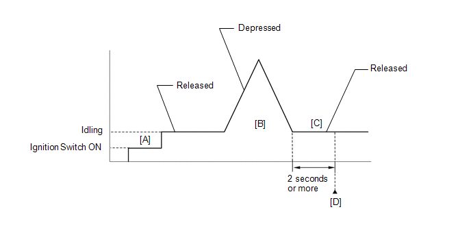
- Turn the ignition switch to ON [A].
- Turn the GTS on.
- Start the engine.
- With the vehicle stationary, fully depress and release the accelerator pedal [B].
- Idle the engine for 2 seconds or more [C].
- Enter the following menus: Powertrain / Engine / Trouble Codes [D].
-
Read the pending DTCs.
HINT:
- If a pending DTC is output, the system is malfunctioning.
- If a pending DTC is not output, perform the following procedure.
- Enter the following menus: Powertrain / Engine / Utility / All Readiness.
- Input the DTC: P21352B.
-
Check the DTC judgment result.
GTS Display
Description
NORMAL
- DTC judgment completed
- System normal
ABNORMAL
- DTC judgment completed
- System abnormal
INCOMPLETE
- DTC judgment not completed
- Perform driving pattern after confirming DTC enabling conditions
HINT:
- If the judgment result is NORMAL, the system is normal.
- If the judgment result is ABNORMAL, the system is malfunctioning.
- If the judgment result is INCOMPLETE, perform steps [B] through [D] again.
FAIL-SAFE
When this DTC is stored, the ECM enters fail-safe mode. During fail-safe mode, the ECM cuts the current to the throttle actuator, and the throttle valve is returned to a 7.5° throttle valve opening angle by the return spring. The ECM then adjusts the engine output by controlling the fuel injection (intermittent fuel-cut) and ignition timing, in accordance with the accelerator pedal angle, to allow the vehicle to continue running at a minimal speed. If the accelerator pedal is depressed firmly and gently, the vehicle can be driven slowly.
Fail-safe mode continues until a pass condition is detected, and the ignition switch is turned off.
WIRING DIAGRAM
Refer to DTC P012011.
Click here

CAUTION / NOTICE / HINT
HINT:
Read Freeze Frame Data using the GTS. The ECM records vehicle and driving condition information as Freeze Frame Data the moment a DTC is stored. When troubleshooting, Freeze Frame Data can help determine if the vehicle was moving or stationary, if the engine was warmed up or not, if the air fuel ratio was lean or rich, and other data from the time the malfunction occurred.
PROCEDURE
| 1. | READ VALUE USING GTS (THROTTLE POSITION SENSOR VOLTAGE) |
(a) Read the values displayed on the GTS.
Powertrain > Engine > Data List| Tester Display |
|---|
| Throttle Position Sensor No.1 Voltage |
| Throttle Position Sensor No.2 Voltage |
| Result | Proceed to |
|---|---|
| The value of Throttle Position Sensor No.1 Voltage and Throttle Position Sensor No.2 Voltage are below 0.56 V | A |
| The value of Throttle Position Sensor No.1 Voltage and Throttle Position Sensor No.2 Voltage are higher than 4.535 V | B |
| The value of Throttle Position Sensor No.1 Voltage and Throttle Position Sensor No.2 Voltage are 0.56 V or higher, and 4.535 V or less | C |
| B |
 | GO TO STEP 4 |
| C |
 | GO TO STEP 6 |
|

| 2. | CHECK HARNESS AND CONNECTOR (THROTTLE POSITION SENSOR - ECM) |
(a) Disconnect the throttle body with motor assembly connector.
(b) Disconnect the ECM connector.
(c) Measure the resistance according to the value(s) in the table below.
Standard Resistance:
| Tester Connection | Condition | Specified Condition |
|---|---|---|
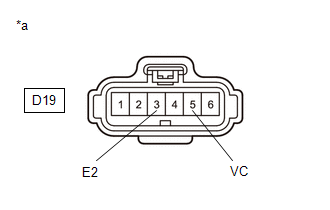
| D19-5(VC) - D104-109(VCTA) | Always | Below 1 Ω |
| D19-6(VTA) - D104-108(VTA1) | Always | Below 1 Ω |
| D19-4(VTA2) - D104-87(VTA2) | Always | Below 1 Ω |
| D19-3(E2) - D104-110(ETA) | Always | Below 1 Ω |
| D19-5(VC) or D104-109(VCTA) - Body ground and other terminals | Always | 10 kΩ or higher |
| D19-6(VTA) or D104-108(VTA1) - Body ground and other terminals | Always | 10 kΩ or higher |
| D19-4(VTA2) or D104-87(VTA2) - Body ground and other terminals | Always | 10 kΩ or higher |
| NG |
 | REPAIR OR REPLACE HARNESS OR CONNECTOR |
|

| 3. | INSPECT TERMINAL VOLTAGE (POWER SOURCE OF THROTTLE POSITION SENSOR) |
(a) Disconnect the throttle body with motor assembly connector.
(b) Turn the ignition switch to ON.
| (c) Measure the voltage according to the value(s) in the table below. Standard Voltage:
|
|
| OK |
 | REPLACE THROTTLE BODY WITH MOTOR ASSEMBLY |
| NG |
 | REPLACE ECM |
| 4. | CHECK HARNESS AND CONNECTOR (GROUND CIRCUIT) |
HINT:
Make sure that the connector is properly connected. If it is not, securely connect it and check for DTCs again.
(a) Disconnect the throttle body with motor assembly connector.
(b) Measure the resistance according to the value(s) in the table below.
Standard Resistance:
| Tester Connection | Condition | Specified Condition |
|---|---|---|
| D19-3(E2) - Body ground | Always | Below 1 Ω |
| OK |
 | REPLACE THROTTLE BODY WITH MOTOR ASSEMBLY |
|

| 5. | CHECK HARNESS AND CONNECTOR (THROTTLE POSITION SENSOR - ECM) |
(a) Disconnect the throttle body with motor assembly connector.
(b) Disconnect the ECM connector.
(c) Measure the resistance according to the value(s) in the table below.
Standard Resistance:
| Tester Connection | Condition | Specified Condition |
|---|---|---|
| D19-5(VC) - D104-109(VCTA) | Always | Below 1 Ω |
| D19-6(VTA) - D104-108(VTA1) | Always | Below 1 Ω |
| D19-4(VTA2) - D104-87(VTA2) | Always | Below 1 Ω |
| D19-3(E2) - D104-110(ETA) | Always | Below 1 Ω |
| D19-5(VC) or D104-109(VCTA) - Other terminals | Always | 10 kΩ or higher |
| D19-6(VTA) or D104-108(VTA1) - Other terminals | Always | 10 kΩ or higher |
| D19-4(VTA2) or D104-87(VTA2) - Other terminals | Always | 10 kΩ or higher |
| OK |
 | REPLACE ECM |
| NG |
 | REPAIR OR REPLACE HARNESS OR CONNECTOR |
| 6. | CHECK HARNESS AND CONNECTOR (SHORT CIRCUIT) |
(a) Disconnect the throttle body with motor assembly connector.
(b) Measure the resistance according to the value(s) in the table below.
Standard Resistance:
| Tester Connection | Condition | Specified Condition |
|---|---|---|
| D19-6(VTA) - D19-4(VTA2) | Always | 10 kΩ or higher |
| OK |
 | REPLACE THROTTLE BODY WITH MOTOR ASSEMBLY |
|

| 7. | CHECK HARNESS AND CONNECTOR (SHORT CIRCUIT) |
(a) Disconnect the throttle body with motor assembly connector.
(b) Disconnect the ECM connector.
(c) Measure the resistance according to the value(s) in the table below.
Standard Resistance:
| Tester Connection | Condition | Specified Condition |
|---|---|---|
| D19-6(VTA) - D19-4(VTA2) | Always | 10 kΩ or higher |
HINT:
If the resistance changes when the ECM connector is disconnected, there is an internal short in the ECM.
| OK |
 | REPLACE ECM |
| NG |
 | REPAIR OR REPLACE HARNESS OR CONNECTOR (THROTTLE POSITION SENSOR - ECM) |
 Throttle/Pedal Position Sensor/Switch "D" Circuit Short to Battery (P212012,P212014,P21201C,P21201F,P212099,P212512,P212514,P21251F,P21382B)
DESCRIPTION HINT: These DTCs relate to the accelerator pedal position sensor. The accelerator pedal position sensor is built into the accelerator pedal sensor assembly and has 2 sensor circuits: VPA (main) and VPA2 (sub)...
 A/F (O2) Sensor Signal Biased/Stuck Lean Bank 1 Sensor 1 Circuit Current Above Threshold (P219519,P219524,P219618,P219623)
DESCRIPTION Refer to DTC P003012. Click here
DTC No. Detection Item DTC Detection Condition Trouble Area MIL Note P219519 A/F (O2) Sensor Signal Biased/Stuck Lean Bank 1 Sensor 1 Circuit Current Above Threshold While the fuel-cut operation is performed (during vehicle deceleration), the air fuel ratio sensor (sensor 1) current is 2...
Other information:
Toyota Yaris XP210 (2020-2025) Reapir and Service Manual: Check For Intermittent Problems
CHECK FOR INTERMITTENT PROBLEMS HINT: Inspect the vehicle ECM using check mode. Intermittent problems are easier to detect with the GTS when the ECM is in check mode. In check mode, the ECM uses 1 trip detection logic, which is more sensitive to malfunctions than normal mode (default), which uses 2 trip detection logic...
Toyota Yaris XP210 (2020-2025) Owner's Manual: Jam-safe window
If foreign matter is detected between the window and the window frame while the window is closing automatically, the window stops closing and automatically opens partway. Jam-safe window The jam-safe function may operate under the following conditions A strong impact is detected while the window is closing automatically...
Categories
- Manuals Home
- Toyota Yaris Owners Manual
- Toyota Yaris Service Manual
- Immobilizer System
- Engine & Hybrid System
- Engine Start Function When Key Battery is Dead
- New on site
- Most important about car
Liftgate/Trunk Lid
WARNING
Never allow a person to ride in the luggage compartment/trunk
Allowing a person to ride in the luggage compartment/trunk is dangerous. The person in the luggage compartment/trunk could be seriously injured or killed during sudden braking or a collision.
Do not drive with the liftgate/trunk lid open