Toyota Yaris: Sfi System / A/F (O2) Sensor Signal Biased/Stuck Lean Bank 1 Sensor 1 Circuit Current Above Threshold (P219519,P219524,P219618,P219623)
DESCRIPTION
Refer to DTC P003012.
Click here

| DTC No. | Detection Item | DTC Detection Condition | Trouble Area | MIL | Note |
|---|---|---|---|---|---|
| P219519 | A/F (O2) Sensor Signal Biased/Stuck Lean Bank 1 Sensor 1 Circuit Current Above Threshold | While the fuel-cut operation is performed (during vehicle deceleration), the air fuel ratio sensor (sensor 1) current is 2.2 mA or more for 3 seconds (2 trip detection logic). |
| Comes on | SAE: P2195 |
| P219524 | A/F (O2) Sensor Signal Biased/Stuck Lean Bank 1 Sensor 1 Signal Stuck High | Both of the following conditions are met for 5 seconds or more (2 trip detection logic):
|
| Comes on | SAE: P2195 |
| P219618 | A/F (O2) Sensor Signal Biased/Stuck Rich Bank 1 Sensor 1 Circuit Current Below Threshold | While the fuel-cut operation is performed (during vehicle deceleration), the air fuel ratio sensor (sensor 1) current is less than 0.47 mA for 3 seconds (2 trip detection logic). |
| Comes on | SAE: P2196 |
| P219623 | A/F (O2) Sensor Signal Biased/Stuck Rich Bank 1 Sensor 1 Signal Stuck Low | Both of the following conditions are met for 5 seconds or more (2 trip detection logic):
|
| Comes on | SAE: P2196 |
HINT:
- When any of these DTCs are stored, check the air fuel ratio sensor (sensor 1) current output by entering the following menus on the GTS: Powertrain / Engine / Data List / A/F (O2) Sensor Current B1S1.
- Short-term fuel trim values can also be read using the GTS.
- If an air fuel ratio sensor (sensor 1) malfunction is detected, the ECM will store a DTC.
MONITOR DESCRIPTION
Air Fuel Ratio Sensor (Sensor 1) Low/High Current:Under air fuel ratio feedback control, if the air fuel ratio sensor (sensor 1) output current is less than -0.1883 mA (very rich condition) for 5 seconds despite the air fuel ratio sensor (sensor 2) output current being -0.0852 mA or more, the ECM stores DTC P219623. Alternatively, if the air fuel ratio sensor (sensor 1) output current is more than 0.1883 mA (very lean condition) for 5 seconds despite the air fuel ratio sensor (sensor 2) output current being less than 0.0551 mA, DTC P219524 is stored.
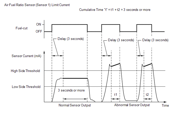
Air Fuel Ratio Sensor (Sensor 1) Limit Current:The ECM monitors the air fuel ratio sensor (sensor 1) current during fuel-cut and detects any abnormal current values.
If the air fuel ratio sensor (sensor 1) output is 2.2 mA or more for more than 3 seconds of cumulative time, the ECM interprets this as a malfunction in the air fuel ratio sensor (sensor 1) and stores DTC P219519 (stuck on high side). If the air fuel ratio sensor (sensor 1) output is less than 0.47 mA for more than 3 seconds of cumulative time, the ECM stores DTC P219618 (stuck on low side).
MONITOR STRATEGY
| Required Sensors/Components (Main) | Air fuel ratio sensor (sensor 1) |
| Required Sensors/Components (Related) | Air fuel ratio sensor (sensor 2) |
| Frequency of Operation | Continuous: Sensor low/high current Once per driving cycle: Sensor limit current |
TYPICAL ENABLING CONDITIONS
Air Fuel Ratio Sensor (Sensor 1) Low/High Current| Time after engine start | 30 seconds or more |
| Auxiliary battery voltage | 11 V or higher |
| Air fuel ratio sensor (sensor 1) status | Activated |
| Fuel system status | Closed-loop |
| Auxiliary battery voltage | 11 V or higher |
| Engine coolant temperature | 75°C (167°F) or higher |
| Atmospheric pressure | 76 kPa(abs) [11 psi(abs)] or higher |
| Air fuel ratio sensor (sensor 1) status | Activated |
| Continuous time of fuel-cut | 3 seconds or more, and less than 10 seconds |
CONFIRMATION DRIVING PATTERN
- Connect the GTS to the DLC3.
- Turn the ignition switch to ON.
- Turn the GTS on.
- Clear the DTCs (even if no DTCs are stored, perform the clear DTC procedure).
- Turn the ignition switch off and wait for at least 30 seconds.
- Turn the ignition switch to ON.
- Turn the GTS on.
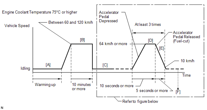
- Start the engine and warm it up until the engine coolant temperature reaches 75°C (167°F) or higher [A].
-
Drive the vehicle at a speed between 60 and 120 km/h (37 and 75 mph) for at least 10 minutes [B].
CAUTION:
When performing the confirmation driving pattern, obey all speed limits and traffic laws.
- Using the GTS, enter the following menus to check the fuel-cut status: Powertrain / Engine / Data List / Idle Fuel Cut.
-
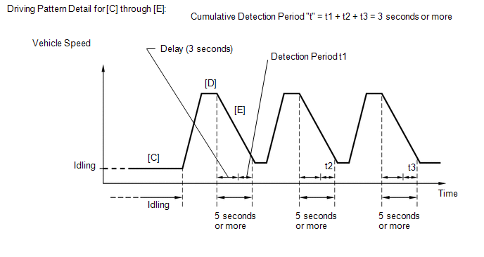
With shift lever in 2nd gear [C], accelerate the vehicle to 64 km/h (40 mph) or more by depressing the accelerator pedal for at least 10 seconds [D].
CAUTION:
When performing the confirmation driving pattern, obey all speed limits and traffic laws.
-
Soon after performing step [D] above, release the accelerator pedal for at least 5 seconds without depressing the brake pedal in order to execute fuel-cut control [E].
HINT:
While "Idle Fuel Cut" on the Data List is ON, fuel-cut control is being executed.
- Allow the vehicle to decelerate until the vehicle speed decreases to less than 10 km/h (6 mph).
- Repeat steps [C] through [E] above at least 3 times in one driving cycle.
- Enter the following menus: Powertrain / Engine / Trouble Codes [F].
-
Read the pending DTCs.
HINT:
- If a pending DTC is output, the system is malfunctioning.
- If a pending DTC is not output, perform the following procedure.
- Enter the following menus: Powertrain / Engine / Utility / All Readiness.
- Input the DTC: P219519, P219524, P219618 or P219623.
-
Check the DTC judgment result.
GTS Display
Description
NORMAL
- DTC judgment completed
- System normal
ABNORMAL
- DTC judgment completed
- System abnormal
INCOMPLETE
- DTC judgment not completed
- Perform driving pattern after confirming DTC enabling conditions
HINT:
- If the judgment result is NORMAL, the system is normal.
- If the judgment result is ABNORMAL, the system has a malfunction.
- If the judgment result is INCOMPLETE, perform steps [B] through [F] again.
WIRING DIAGRAM
Refer to DTC P003012.
Click here

CAUTION / NOTICE / HINT
NOTICE:
Inspect the fuses for circuits related to this system before performing the following procedure.
HINT:
- A low air fuel ratio sensor (sensor 1) current could be caused by a rich air fuel mixture. Check for conditions that would cause the engine to run rich.
- A high air fuel ratio sensor (sensor 1) current could be caused by a lean air fuel mixture. Check for conditions that would cause the engine to run lean.
- Read Freeze Frame Data using the GTS. The ECM records vehicle and driving condition information as Freeze Frame Data the moment a DTC is stored. When troubleshooting, Freeze Frame Data can help determine if the vehicle was moving or stationary, if the engine was warmed up or not, if the air fuel ratio was lean or rich, and other data from the time the malfunction occurred.
- Sensor 1 refers to the sensor closest to the engine assembly.
- Sensor 2 refers to the sensor farthest away from the engine assembly.
PROCEDURE
| 1. | CHECK ANY OTHER DTCS OUTPUT (IN ADDITION TO DTC P219519, P219524, P219618 OR P219623) |
(a) Read the DTCs.
Powertrain > Engine > Trouble Codes| Result | Proceed to |
|---|---|
| P219519, P219524, P219618 or P219623 is output | A |
| P219519, P219524, P219618 or P219623 and other DTCs are output | B |
HINT:
If any DTCs other than P219519, P219524, P219618 or P219623 are output, troubleshoot those DTCs first.
| B |
 | GO TO DTC CHART |
|

| 2. | CONFIRM IF VEHICLE HAS RUN OUT OF FUEL IN PAST |
(a) Has the vehicle run out of fuel in the past?
| NO |
 | GO TO STEP 5 |
|

| 3. | CLEAR DTC |
(a) Clear the DTCs.
Powertrain > Engine > Clear DTCs(b) Turn the ignition switch off and wait for at least 30 seconds.
|

| 4. | CHECK WHETHER DTC OUTPUT RECURS (DTC P219519, P219524, P219618 OR P219623) |
(a) Drive the vehicle in accordance with the driving pattern described in Confirmation Driving Pattern.
(b) Enter the following menus.
Powertrain > Engine > Utility| Tester Display |
|---|
| All Readiness |
(c) Input the DTC: P219519, P219524, P219618 or P219623.
(d) Check the DTC judgment result.
| Result | Proceed to |
|---|---|
| NORMAL (DTCs are not output) | A |
| ABNORMAL (P219519, P219524, P219618 or P2196233 is output) | B |
| A |
 | DTC CAUSED BY RUNNING OUT OF FUEL |
| B |
 | GO TO STEP 5 |
| 5. | CLEAR DTC |
(a) Clear the DTCs.
Powertrain > Engine > Clear DTCs(b) Turn the ignition switch off and wait for at least 30 seconds.
|

| 6. | READ VALUE USING GTS (A/F (O2) SENSOR CURRENT) |
(a) Drive the vehicle in accordance with the driving pattern described in Confirmation Driving Pattern.
(b) Enter the following menus.
Powertrain > Engine > Data List| Tester Display |
|---|
| A/F (O2) Sensor Current B1S1 |
(c) Check the test value of the air fuel ratio sensor (sensor 1) output current during fuel-cut, referring to the Driving Pattern Detail for [C] through [E] in the Confirmation Driving Pattern.
HINT:
- To measure the air fuel ratio sensor (sensor 1) current precisely, perform the fuel-cut operation as long as possible.
- If it is difficult to measure the air fuel ratio sensor (sensor 1) current, use the snapshot function of the GTS.
| Test Value | Proceed to |
|---|---|
| Within normal range (0.47 mA or more, and less than 2.2 mA) | A |
| Outside normal range (Less than 0.47 mA, or 2.2 mA or more) | B |
| B |
 | GO TO STEP 15 |
|

| 7. | PERFORM ACTIVE TEST USING GTS (CONTROL THE INJECTION VOLUME FOR A/F SENSOR) |
(a) Start the engine and warm it up until the engine coolant temperature reaches 75°C (167°F) or higher.
(b) Warm up the air fuel ratio sensors at an engine speed of 2500 rpm for 90 seconds.
(c) Enter the following menus.
Powertrain > Engine > Active Test| Active Test Display |
|---|
| Control the Injection Volume for A/F Sensor |
| Data List Display |
|---|
| A/F (O2) Sensor Current B1S1 |
| A/F (O2) Sensor Current B1S2 |
(d) Perform the Control the Injection Volume for A/F Sensor operation with the engine idling.
(e) Monitor the output currents of the air fuel ratio sensors (A/F (O2) Sensor Current B1S1 and A/F (O2) Sensor Current B1S2) displayed on the GTS.
HINT:
- The Control the Injection Volume for A/F Sensor operation lowers the fuel injection volume by 12.5% or increases the injection volume by 12.5%.
- The air fuel ratio sensor (sensor 1) has an output delay of a few seconds and the air fuel ratio sensor (sensor 2) has a maximum output delay of approximately 20 seconds.
- If the sensor output current does not change (almost no reaction) while performing the Active Test, the sensor may be malfunctioning.
| GTS Display (Sensor) | Injection Volume | Status | Current |
|---|---|---|---|
| A/F (O2) Sensor Current B1S1 (Air fuel ratio sensor (sensor 1)) | 12.5% | Rich | Below -0.075 mA |
| -12.5% | Lean | More than 0.037 mA | |
| A/F (O2) Sensor Current B1S2 (Air fuel ratio sensor (sensor 2)) | 12.5% | Rich | Below -0.86 mA |
| -12.5% | Lean | More than 0.33 mA |
| Status of A/F (O2) Sensor Current B1S1 | Status of A/F (O2) Sensor Current B1S2 | Air Fuel Ratio Condition and Air Fuel Ratio Sensor (Sensor 1) Condition | Proceed to |
|---|---|---|---|
| Lean | Lean | Actual air fuel ratio lean | A |
| Rich | Rich | Actual air fuel ratio rich | |
| Lean | Lean/Rich | Air fuel ratio sensor (sensor 1) malfunction | B |
| Rich | Lean/Rich | Air fuel ratio sensor (sensor 1) malfunction | |
| Lean/Rich | Lean/Rich | Normal |
- Lean: During the Control the Injection Volume for A/F Sensor Active Test, the air fuel ratio sensor (sensor 1) output current (A/F (O2) Sensor Current B1S1) is consistently more than 0.037 mA, and the air fuel ratio sensor (sensor 2) output current (A/F (O2) Sensor Current B1S2) is consistently more than 0.33 mA.
- Rich: During the Control the Injection Volume for A/F Sensor Active Test, the air fuel ratio sensor (sensor 1) output current (A/F (O2) Sensor Current B1S1) is consistently below -0.075 mA, and the air fuel ratio sensor (sensor 2) output current (A/F (O2) Sensor Current B1S2) is consistently below -0.86 mA.
- Lean/Rich: During the Control the Injection Volume for A/F Sensor Active Test, the output current of the air fuel ratio sensor (sensor 1) or air fuel ratio sensor (sensor 2) alternate correctly.
HINT:
Refer to "Data List / Active Test" [A/F (O2) Sensor Current B1S1 and A/F (O2) Sensor Current B1S2].
Click here

| B |
 | GO TO STEP 15 |
|

| 8. | CHECK INTAKE SYSTEM |
(a) Check the intake system for vacuum leaks.
Click here

OK:
No leaks in the intake system.
HINT:
Perform "Inspection After Repair" after repairing or replacing the intake system.
Click here

| NG |
 | REPAIR OR REPLACE INTAKE SYSTEM |
|

| 9. | CHECK FOR EXHAUST GAS LEAK |
(a) Check for exhaust gas leaks.
OK:
No gas leaks in exhaust system.
HINT:
Perform "Inspection After Repair" after repairing or replacing the exhaust system.
Click here

| NG |
 | REPAIR OR REPLACE EXHAUST SYSTEM |
|

| 10. | CHECK FUEL PRESSURE (FOR LOW PRESSURE SIDE) |
(a) Check the fuel pressure (for low pressure side).
Click here

| NG |
 | GO TO STEP 14 |
|

| 11. | INSPECT PORT FUEL INJECTOR ASSEMBLY |
(a) Inspect the port fuel injector assembly (whether fuel volume is high or low, and whether injection pattern is poor).
Click here

HINT:
Perform "Inspection After Repair" after replacing the port fuel injector assembly.
Click here

| NG |
 | REPLACE PORT FUEL INJECTOR ASSEMBLY |
|

| 12. | READ VALUE USING GTS (FUEL PRESSURE (HIGH)) |
(a) Start the engine.
(b) Enter the following menus.
Powertrain > Engine > Data List| Tester Display |
|---|
| Fuel Pressure (High) |
| Injection Mode |
(c) Start the engine and warm it up until the engine coolant temperature is 75°C (167°F) or higher with all the accessories switched off.
(d) According to the display on the GTS, read the Data List.
Standard:
| GTS Display | Condition | Specified Condition |
|---|---|---|
| Fuel Pressure (High) |
| 2800 to 20000 kPag |
| NG |
 | REPAIR OR REPLACE FUEL SYSTEM (FOR HIGH PRESSURE SIDE) |
|

| 13. | INSPECT DIRECT FUEL INJECTOR ASSEMBLY |
Click here

HINT:
Perform "Inspection After Repair" after replacing the direct fuel injector assembly.
Click here

| OK |
 | GO TO STEP 15 |
| NG |
 | REPLACE DIRECT FUEL INJECTOR ASSEMBLY |
| 14. | CHECK FUEL LINE |
(a) Check the fuel lines for leaks or blockage.
HINT:
Perform "Inspection After Repair" after replacing the fuel pump (for low pressure side).
Click here

| OK |
 | GO TO FUEL PUMP CONTROL CIRCUIT |
| NG |
 | REPAIR OR REPLACE FUEL LINE |
| 15. | REPLACE AIR FUEL RATIO SENSOR (SENSOR 1) |
Click here

HINT:
Perform "Inspection After Repair" after replacing the air fuel ratio sensor (sensor 1).
Click here

|

| 16. | CLEAR DTC |
(a) Clear the DTCs.
Powertrain > Engine > Clear DTCs(b) Turn the ignition switch off and wait for at least 30 seconds.
|

| 17. | CHECK WHETHER DTC OUTPUT RECURS (DTC P219519, P219524, P219618 OR P219623) |
(a) Drive the vehicle in accordance with the driving pattern described in Confirmation Driving Pattern.
(b) Enter the following menus.
Powertrain > Engine > Utility| Tester Display |
|---|
| All Readiness |
(c) Input the DTC: P219519, P219524, P219618 or P219623.
(d) Check the DTC judgment result.
| Result | Proceed to |
|---|---|
| NORMAL (DTCs are not output) | A |
| ABNORMAL (P219519, P219524, P219618 or P219623 is output) | B |
| A |
 | END |
| B |
 | REPLACE ECM |
 Throttle/Pedal Position Sensor/Switch "A"/"B" Voltage Correlation Signal Cross Coupled (P21352B)
DESCRIPTION Refer to DTC P012011. Click here
DTC No. Detection Item DTC Detection Condition Trouble Area MIL Note P21352B Throttle/Pedal Position Sensor/Switch "A"/"B" Voltage Correlation Signal Cross Coupled The difference between the output voltage of VTA1 and VTA2 is 0...
 Cylinder 1 Injector "B" Circuit Open (P21CF13,P21D013,P21D113)
DESCRIPTION The D-4S system has two injection systems. One is an in-cylinder direct injection system that directly injects pressurized fuel into the combustion chamber...
Other information:
Toyota Yaris XP210 (2020-2026) Reapir and Service Manual: Inspection
INSPECTION PROCEDURE 1. INSPECT NO. 1 OUTPUT SHAFT (a) Check the No. 1 output shaft for wear and damage. (b) Using a dial indicator, check the No. 1 output shaft runout. Maximum Runout: 0.01 mm (0.000394 in.) (1) If the runout exceeds the maximum, replace the No...
Toyota Yaris XP210 (2020-2026) Owner's Manual: Installing Child-Restraint Systems
Accident statistics reveal that a child is safer in the rear seat. The front passenger’s seat is clearly the worst choice for any child under 12, and with rear-facing child-restraint systems it is clearly unsafe due to air bags. Some child-restraint systems now come with tethers and therefore must be installed on the seats that take tethers to be effective...
Categories
- Manuals Home
- Toyota Yaris Owners Manual
- Toyota Yaris Service Manual
- Engine & Hybrid System
- To Set Speed
- Diagnostic Trouble Code Chart
- New on site
- Most important about car
Refueling
Before refueling, close all the doors, windows, and the liftgate/trunk lid, and switch the ignition OFF.
To open the fuel-filler lid, pull the remote fuel-filler lid release.
