Toyota Yaris: Sfi System / Cylinder 1 Injector "B" Circuit Open (P21CF13,P21D013,P21D113)
DESCRIPTION
The D-4S system has two injection systems. One is an in-cylinder direct injection system that directly injects pressurized fuel into the combustion chamber. The other is an intake port injection system. The ECM determines the percentage of direct injection and port injection necessary in accordance with the engine speed and load.
| DTC No. | Detection Item | DTC Detection Condition | Trouble Area | MIL | Note |
|---|---|---|---|---|---|
| P21CF13 | Cylinder 1 Injector "B" Circuit Open | Open or short in port fuel injector assembly (1 trip detection logic). |
| Comes on | SAE: P21CF |
| P21D013 | Cylinder 2 Injector "B" Circuit Open | Open or short in port fuel injector assembly (1 trip detection logic). |
| Comes on | SAE: P21D0 |
| P21D113 | Cylinder 3 Injector "B" Circuit Open | Open or short in port fuel injector assembly (1 trip detection logic). |
| Comes on | SAE: P21D1 |
MONITOR DESCRIPTION
The ECM monitors the injection control of the port fuel injector assemblies. If a malfunction is detected in a port fuel injector assembly circuit, the ECM cancels the injection control for the corresponding cylinder, illuminates the MIL and stores a DTC.
MONITOR STRATEGY
| Required Sensors/Components | Port fuel injector assembly (cylinder 1 to 6) |
| Frequency of Operation | Continuous |
CONFIRMATION DRIVING PATTERN
- Connect the GTS to the DLC3.
- Turn the ignition switch to ON.
- Turn the GTS on.
- Clear the DTCs (even if no DTCs are stored, perform the clear DTC procedure).
- Turn the ignition switch off and wait for at least 30 seconds.
- Start the engine [A].
- Idle the engine for 3 minutes or more [B].
- Turn the GTS on.
- Enter the following menus: Powertrain / Engine / Trouble Codes [C].
-
Read the DTCs.
HINT:
- If a pending DTC is output, the system is malfunctioning.
- If a pending DTC is not output, perform the following procedure.
- Enter the following menus: Powertrain / Engine / Utility / All Readiness.
- Input the DTC: P21CF13, P21D013 or P21D113.
-
Check the DTC judgment result.
GTS Display
Description
NORMAL
- DTC judgment completed
- System normal
ABNORMAL
- DTC judgment completed
- System abnormal
INCOMPLETE
- DTC judgment not completed
- Perform driving pattern after confirming DTC enabling conditions
HINT:
- If the judgment result is NORMAL, the system is normal.
- If the judgment result is ABNORMAL, the system has a malfunction.
- If the judgment result is INCOMPLETE, perform steps [B] through [C] again.
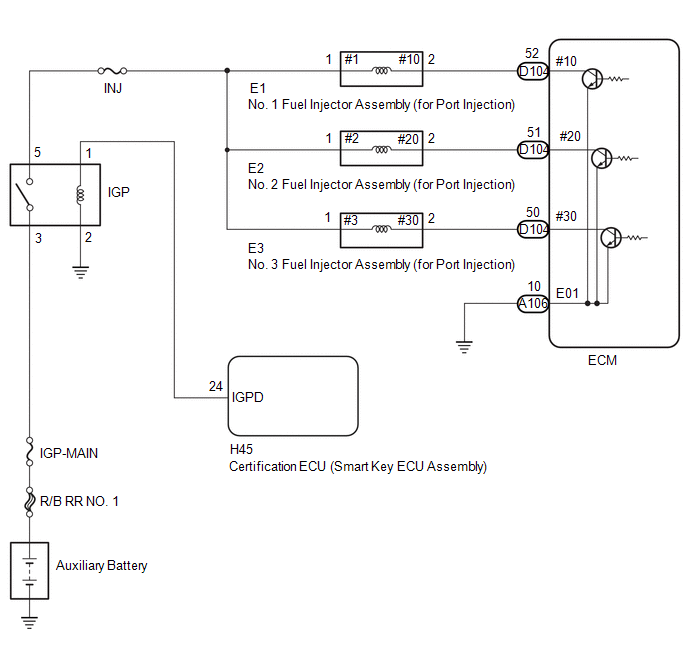
WIRING DIAGRAM
CAUTION / NOTICE / HINT
NOTICE:
Inspect the fuses for circuits related to this system before performing the following procedure.
HINT:
Read Freeze Frame Data using the GTS. The ECM records vehicle and driving condition information as Freeze Frame Data the moment a DTC is stored. When troubleshooting, Freeze Frame Data can help determine if the vehicle was moving or stationary, if the engine was warmed up or not, if the air fuel ratio was lean or rich, and other data from the time the malfunction occurred.
PROCEDURE
| 1. | CHECK DTCS OUTPUT (IN ADDITION TO DTC P21CF13, P21D013 OR P21D113) |
(a) Read the DTCs.
Powertrain > Engine > Trouble Codes| Result | Proceed to |
|---|---|
| P21CF13, P21D013 or P21D113 is output | A |
| P21CF13, P21D013 or P21D113 are output | B |
| B |
 | REPAIR OR REPLACE HARNESS OR CONNECTOR (IGP RELAY - PORT FUEL INJECTOR ASSEMBLY) |
|

| 2. | CHECK TERMINAL VOLTAGE (POWER SOURCE OF PORT FUEL INJECTOR ASSEMBLY) |
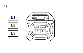
(a) Disconnect the port fuel injector assembly connector.
(b) Turn the ignition switch to ON.
| (c) Measure the voltage according to the value(s) in the table below Standard Voltage:
|
|
| NG |
 | REPAIR OR REPLACE HARNESS OR CONNECTOR (IGP RELAY - PORT FUEL INJECTOR ASSEMBLY) |
|

| 3. | CHECK HARNESS AND CONNECTOR (PORT FUEL INJECTOR ASSEMBLY - ECM) |
(a) Disconnect the ECM connector.
(b) Disconnect the port fuel injector assembly connector.
(c) Measure the resistance according to the value(s) in the table below.
Standard Resistance:
| Tester Connection | Condition | Specified Condition |
|---|---|---|
| E1-2(#10) - D104-52(#10) | Always | Below 1 Ω |
| E2-2(#20) - D104-51(#20) | Always | Below 1 Ω |
| E3-2(#30) - D104-50(#30) | Always | Below 1 Ω |
| E1-2(#10) or D104-52(#10) - Body ground and other terminals | Always | 10 kΩ or higher |
| E2-2(#20) or D104-51(#20) - Body ground and other terminals | Always | 10 kΩ or higher |
| E3-2(#30) or D104-50(#30) - Body ground and other terminals | Always | 10 kΩ or higher |
| NG |
 | REPAIR OR REPLACE HARNESS OR CONNECTOR |
|

| 4. | INSPECT PORT FUEL INJECTOR ASSEMBLY (RESISTANCE) |
Click here

HINT:
Perform "Inspection After Repair" after replacing the port fuel injector assembly.
Click here

| OK |
 | REPLACE ECM |
| NG |
 | REPLACE PORT FUEL INJECTOR ASSEMBLY |
 A/F (O2) Sensor Signal Biased/Stuck Lean Bank 1 Sensor 1 Circuit Current Above Threshold (P219519,P219524,P219618,P219623)
DESCRIPTION Refer to DTC P003012. Click here
DTC No. Detection Item DTC Detection Condition Trouble Area MIL Note P219519 A/F (O2) Sensor Signal Biased/Stuck Lean Bank 1 Sensor 1 Circuit Current Above Threshold While the fuel-cut operation is performed (during vehicle deceleration), the air fuel ratio sensor (sensor 1) current is 2...
 Barometric Pressure Sensor "A" Circuit Short to Ground (P222611,P222615)
DESCRIPTION The atmospheric pressure sensor is built into the ECM. The ECM provides optimal control in response to atmospheric pressure fluctuations. DTC No...
Other information:
Toyota Yaris XP210 (2020-2026) Reapir and Service Manual: Data List / Active Test
DATA LIST / ACTIVE TEST READ DATA LIST NOTICE: In the table below, the values listed under "Normal Condition" are reference values. Do not depend solely on these reference values when deciding whether a part is faulty or not. HINT: Using the GTS to read the Data List allows values or states of switches, sensors, actuators and other items to be read without removing any parts...
Toyota Yaris XP210 (2020-2026) Reapir and Service Manual: Installation
INSTALLATION PROCEDURE 1. INSTALL BRAKE BOOSTER GASKET (a) Install a new brake booster gasket to the brake booster assembly. 2. INSTALL BRAKE BOOSTER ASSEMBLY (a) Temporarily install the brake booster assembly to the vehicle body. NOTICE: Do not apply excessive force to the brake lines...
Categories
- Manuals Home
- Toyota Yaris Owners Manual
- Toyota Yaris Service Manual
- Auto Lock/Unlock Function
- G16e-gts (engine Mechanical)
- Battery Monitor Module General Electrical Failure (P058A01)
- New on site
- Most important about car
Key Suspend Function
If a key is left in the vehicle, the functions of the key left in the vehicle are temporarily suspended to prevent theft of the vehicle.
To restore the functions, press the unlock button on the functions-suspended key in the vehicle.