Toyota Yaris: Fuel Injector (for Port Injection) / Removal
REMOVAL
CAUTION / NOTICE / HINT
The necessary procedures (adjustment, calibration, initialization or registration) that must be performed after parts are removed and installed, or replaced during fuel injector assembly removal/installation are shown below.
Necessary Procedures After Parts Removed/Installed/Replaced| Replaced Part or Performed Procedure | Necessary Procedure | Effect/Inoperative Function when Necessary Procedure not Performed | Link |
|---|---|---|---|
| Replacement of fuel injector assembly | Inspection after repair |
|
|

CAUTION:
-
Never perform work on fuel system components near any possible ignition sources.
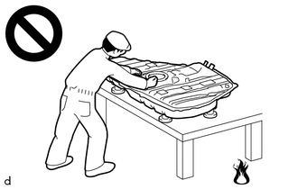
- Vaporized fuel could ignite, resulting in a serious accident.
-
Do not perform work on fuel system components without first disconnecting the cable from the negative (-) auxiliary battery terminal.
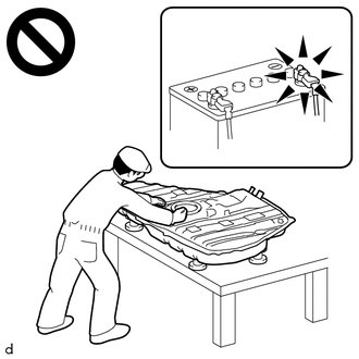
- Sparks could cause vaporized fuel to ignite, resulting in a serious accident.
NOTICE:
- After the ignition switch is turned off, the radio and display receiver assembly records various types of memory and settings. As a result, after turning the ignition switch off, make sure to wait at least 120 seconds before disconnecting the cable from the negative (-) auxiliary battery terminal.
-
This procedure includes the removal of small-head bolts. Refer to Small-Head Bolts of Basic Repair Hint to identify the small-head bolts.
Click here

HINT:
When the cable is disconnected/reconnected to the auxiliary battery terminal, systems temporarily stop operating. However, each system has a function that completes learning the first time the system is used.
-
Learning completes when vehicle is driven
Effect/Inoperative Function When Necessary Procedures are not Performed
Necessary Procedures
Link
Lane tracing assist system
Drive the vehicle straight ahead at 35 km/h (22 mph) or more for 5 second or more.

Pre-collision system
Stop and start system
Drive the vehicle until stop and start control is permitted (approximately 5 to 60 minutes)

-
Learning completes when vehicle is operated normally
Effect/Inoperative Function When Necessary Procedures are not Performed
Necessary Procedures
Link
Power door lock control system
- Back door opener
Perform door unlock operation with door control switch or electrical key transmitter sub-assembly switch.

Air conditioning system
After the ignition switch is turned to ON, the servo motor standard position is recognized.
-
PROCEDURE
1. PRECAUTION
NOTICE:
After turning the ignition switch off, waiting time may be required before disconnecting the cable from the negative (-) auxiliary battery terminal.
Click here

2. DISCHARGE FUEL SYSTEM PRESSURE
Click here

3. REMOVE NO. 1 ENGINE COVER SUB-ASSEMBLY
Click here

4. DISCONNECT ENGINE WIRE
Click here

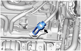
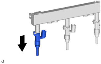
5. REMOVE FUEL PIPE CLAMP
| (a) Remove the fuel pipe clamp from the fuel tube connector. |
|
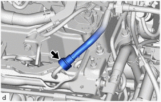
6. DISCONNECT NO. 2 FUEL TUBE SUB-ASSEMBLY
| (a) Disconnect the No. 2 fuel tube sub-assembly from the fuel delivery pipe sub-assembly. Click here
|
|

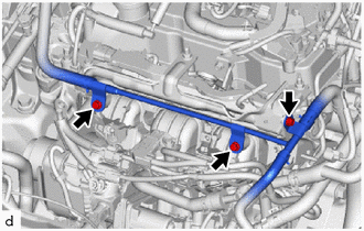
7. DISCONNECT NO. 4 WATER BY-PASS PIPE
| (a) Remove the 3 bolts and No. 4 water by-pass pipe from the cylinder head sub-assembly. |
|
8. REMOVE OIL LEVEL GAUGE SUB-ASSEMBLY
| (a) Remove the oil level gauge sub-assembly. |
|
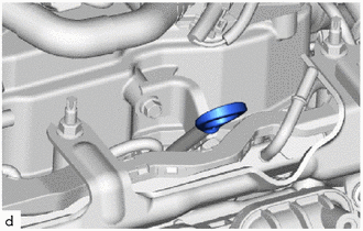
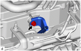
9. REMOVE OIL LEVEL GAUGE GUIDE
| (a) Remove the bolt and oil level gauge guide from the cylinder head sub-assembly. |
|
(b) Remove the O-ring from oil level gauge guide.
10. REMOVE FUEL DELIVERY GUARD
| (a) Disengage the wire harness clamp. |
|
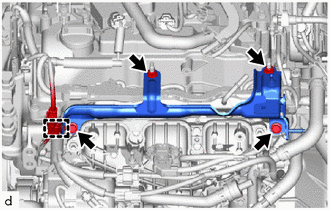
(b) Remove the 2 bolts, 2 nuts and fuel delivery guard.
11. REMOVE FUEL DELIVERY PIPE
| (a) Disconnect the connector. |
|
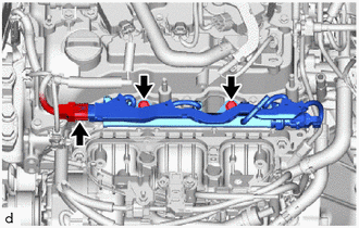
(b) Remove the 2 bolts and fuel delivery pipe with the 3 fuel injector assemblies from the cylinder head sub-assembly.
NOTICE:
Be careful not to drop the fuel injector assemblies when removing the fuel delivery pipe sub-assembly.
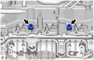
12. REMOVE FUEL DELIVERY SPACER
| (a) Remove the 2 fuel delivery spacers from the cylinder head sub-assembly. |
|
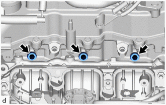
13. REMOVE INJECTOR VIBRATION INSULATOR
| (a) Remove the 3 injector vibration insulators from the cylinder head sub-assembly. |
|
14. REMOVE NO. 5 ENGINE WIRE
| (a) Disconnect the 4 connectors from the 3 fuel injector assemblies and fuel pressure sensor. |
|
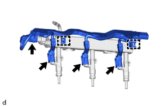
(b) Disengage the 2 clamps to remove the No. 5 engine wire from the fuel delivery pipe.
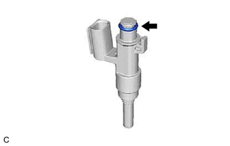
15. REMOVE PORT FUEL INJECTOR ASSEMBLY
| (a) Pull the 3 fuel injector assemblies out of the fuel delivery pipe. |
|
| (b) Remove the O-ring from each fuel injector assembly. |
|
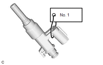
| (c) Attach a tag or label with the corresponding cylinder number to each fuel injector assembly so that they can be installed to their original locations. NOTICE: Cover the fuel injector assemblies with plastic bags to prevent damage and contamination. |
|
 Components
COMPONENTS ILLUSTRATION
*1 PORT FUEL INJECTOR ASSEMBLY *2 NO. 5 ENGINE WIRE *3 INJECTOR VIBRATION INSULATOR *4 FUEL DELIVERY SPACER *5 FUEL DELIVERY PIPE *6 FUEL DELIVERY GUARD *7 OIL LEVEL GAUGE GUIDE *8 OIL LEVEL GAUGE SUB-ASSEMBLY *9 NO...
 Inspection
INSPECTION PROCEDURE 1. INSPECT FUEL INJECTOR ASSEMBLY (a) Check the resistance. (1) Measure the resistance according to the value(s) in the table below...
Other information:
Toyota Yaris XP210 (2020-2026) Reapir and Service Manual: Inspection
INSPECTION PROCEDURE 1. INSPECT OIL PRESSURE AND TEMPERATURE SENSOR (a) Check the oil pressure and temperature sensor output voltage. (1) Apply 5 V between terminals 3 (VC) and 2 (GND). NOTICE: Be careful when connecting the leads as the oil pressure and temperature sensor may be damaged if the leads are connected to the wrong terminals...
Toyota Yaris XP210 (2020-2026) Reapir and Service Manual: Components
COMPONENTS ILLUSTRATION *1 COVER AND DISC CLUTCH SET *2 MANUAL TRANSAXLE ASSEMBLY *3 CLUTCH RELEASE CYLINDER WITH BEARING ASSEMBLY *4 CLUTCH TUBE BOOT *5 CLUTCH RELEASE CYLINDER TO BLEEDER TUBE *6 CLUTCH RELEASE BLEEDER SUB-ASSEMBLY *7 BLEEDER CLUTCH RELEASE TUBE *8 CLAMP *9 CLUTCH RELEASE BEARING PLATE - - Tightening torque for "Major areas involving basic vehicle performance such as moving/turning/stopping": N*m (kgf*cm, ft...
Categories
- Manuals Home
- Toyota Yaris Owners Manual
- Toyota Yaris Service Manual
- Headlights
- G16e-gts (engine Mechanical)
- Opening and Closing the Liftgate/Trunk Lid
- New on site
- Most important about car
Liftgate/Trunk Lid
WARNING
Never allow a person to ride in the luggage compartment/trunk
Allowing a person to ride in the luggage compartment/trunk is dangerous. The person in the luggage compartment/trunk could be seriously injured or killed during sudden braking or a collision.
Do not drive with the liftgate/trunk lid open