Toyota Yaris: Fuel Injector (for Port Injection) / Inspection
INSPECTION
PROCEDURE
1. INSPECT FUEL INJECTOR ASSEMBLY
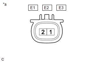
(a) Check the resistance.
| (1) Measure the resistance according to the value(s) in the table below. Standard Resistance:
If the result is not as specified, replace the port fuel injector assembly. |
|
(b) Check the operation.
CAUTION:
Perform the inspection in a well-ventilated area.
Do not perform the inspection near an open flame.
(1) Open the cover of the No. 1 fuel pipe clamp and remove the No. 1 fuel pipe clamp from the fuel tube connector.
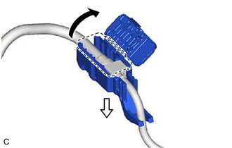
 | Open |
 | Pull |
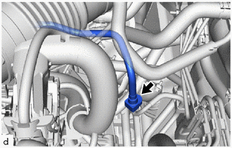
| (2) Disconnect the fuel tube sub-assembly. Click here
|
|

| (3) Connect SST (fuel tube connector) to SST (hose) with SST (hose band), and then connect them to the fuel pipe (vehicle side). SST: 09268-31015 09268-41700 95336-08070 SST: 09268-00010 09268-00030 NOTICE: Make sure the SST (fuel tube connector) O-rings are not damaged and are free of foreign matter as they are used to seal the connections between the fuel tube connector and fuel pipe. |
|
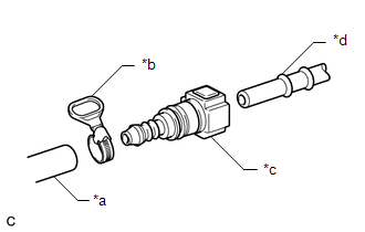
(4) Apply a light coat of gasoline to a new O-ring, and then install the O-ring to the port fuel injector assembly.
| (5) Connect SST (adapter) and SST (hose) to the port fuel injector assembly, and hold the port fuel injector assembly and union with SST (clamp). SST: 09268-31015 09268-41410 09268-41600 09268-41700 95336-08070 |
|
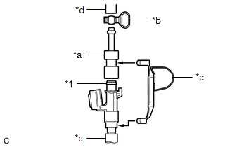
(6) Install a vinyl tube to the port fuel injector assembly.
CAUTION:
Install a suitable vinyl tube to the port fuel injector assembly to prevent fuel from spraying.
| (7) Tie SST (clamp) and SST (adapter) together with SST (tie band) as shown in the illustration. SST: 09268-31015 09268-41800 NOTICE:
HINT: When removing SST (tie band), disengage the lock. |
|
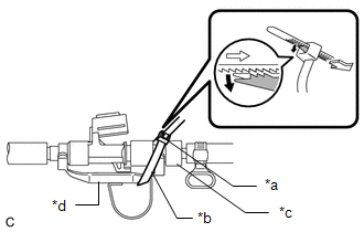
(8) Check that SST (clamp) and SST (adapter) cannot be easily separated.
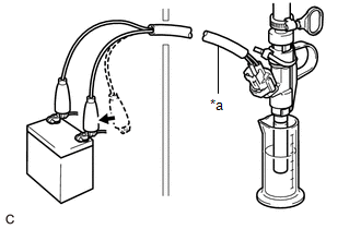
(9) Set the port fuel injector assembly into a graduated cylinder.
(10) Connect the GTS to the DLC3.
(11) Turn the ignition switch to ON.
NOTICE:
Do not start the engine.
(12) Turn the GTS on.
(13) Enter the following menus: Powertrain / Engine / Active Test / Activate the Circuit Relay.
Powertrain > Engine > Active Test| Tester Display |
|---|
| Activate the Circuit Relay |
| (14) Connect SST (EFI inspection wire K) to the port fuel injector assembly and auxiliary battery for 15 seconds, and measure the injection volume with the graduated cylinder. Test each port fuel injector assembly 2 or 3 times. SST: 09842-30110 Standard Injection Volume:
Difference between Each Port Fuel Injector Assembly: 11 cc (0.7 cu.in.) or less NOTICE:
If the result is not as specified, replace the port fuel injector assembly. |
|
(c) Check for leaks.
(1) Disconnect SST (EFI inspection wire K) from the auxiliary battery and check for fuel leaks from the port fuel injector assembly.
Standard Fuel Drop:
1 drop or less per 20 minutes
If the result is not as specified, replace the port fuel injector assembly.
(2) Connect the fuel tube sub-assembly.
Click here

(3) Install the No. 1 fuel pipe clamp to the fuel tube connector and close the cover of the No. 1 fuel pipe clamp.
 Removal
REMOVAL CAUTION / NOTICE / HINT The necessary procedures (adjustment, calibration, initialization or registration) that must be performed after parts are removed and installed, or replaced during fuel injector assembly removal/installation are shown below...
 Installation
INSTALLATION CAUTION / NOTICE / HINT NOTICE: This procedure includes the installation of small-head bolts. Refer to Small-Head Bolts of Basic Repair Hint to identify the small-head bolts...
Other information:
Toyota Yaris XP210 (2020-2026) Reapir and Service Manual: Front Brake Flexible Hose
ComponentsCOMPONENTS ILLUSTRATION *1 FRONT FLEXIBLE HOSE *2 GASKET *3 BRAKE LINE *4 FRONT SPEED SENSOR *5 UNION BOLT - - Tightening torque for "Major areas involving basic vehicle performance such as moving/turning/stopping": N*m (kgf*cm, ft...
Toyota Yaris XP210 (2020-2026) Reapir and Service Manual: Installation
INSTALLATION CAUTION / NOTICE / HINT HINT: Use the same procedure for the RH side and LH side. The following procedure is for the LH side. The front speed sensor rotor is a component of the front axle hub sub-assembly. If the front speed sensor rotor is malfunctioning, replace the front axle hub sub-assembly...
Categories
- Manuals Home
- Toyota Yaris Owners Manual
- Toyota Yaris Service Manual
- Brake System Control Module "A" System Voltage System Voltage Low (C137BA2)
- Fuel Gauge
- Opening and Closing the Liftgate/Trunk Lid
- New on site
- Most important about car
Refueling
Before refueling, close all the doors, windows, and the liftgate/trunk lid, and switch the ignition OFF.
To open the fuel-filler lid, pull the remote fuel-filler lid release.
