Toyota Yaris: Fuel Injector (for Port Injection) / Installation
INSTALLATION
CAUTION / NOTICE / HINT
NOTICE:
This procedure includes the installation of small-head bolts. Refer to Small-Head Bolts of Basic Repair Hint to identify the small-head bolts.
Click here

PROCEDURE
1. INSTALL PORT FUEL INJECTOR ASSEMBLY
HINT:
Perform "Inspection After Repair" after replacing a fuel injector assembly.
Click here

(a) Apply a light coat of spindle oil or gasoline to 3 new O-rings, and install one to each fuel injector assembly.
NOTICE:
Check that there is no damage or foreign matter on the groove of the fuel injector assembly when installing the O-ring to each fuel injector assembly.
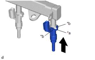
| (b) Install the 3 fuel injector assemblies to the fuel delivery pipe. NOTICE:
|
|
2. INSTALL NO. 5 ENGINE WIRE
(a) Engage the 2 clamps to install the No. 5 engine wire to the fuel delivery pipe.
(b) Connect the 4 connectors to the 3 fuel injector assemblies and fuel pressure sensor.
3. INSTALL INJECTOR VIBRATION INSULATOR
(a) Install 3 new injector vibration insulators to the cylinder head sub-assembly.
4. INSTALL FUEL DELIVERY SPACER
(a) Install the 2 fuel delivery spacers to the cylinder head sub-assembly.
5. INSTALL FUEL DELIVERY PIPE
(a) Place the fuel delivery pipe with the 3 fuel injector assemblies onto the cylinder head sub-assembly.
NOTICE:
Be careful not to drop the fuel injector assemblies when installing the fuel delivery pipe.
(b) Install the fuel delivery pipe with the fuel injector assemblies with the 2 bolts.
Torque:
29 N·m {296 kgf·cm, 21 ft·lbf}
6. INSTALL FUEL DELIVERY GUARD
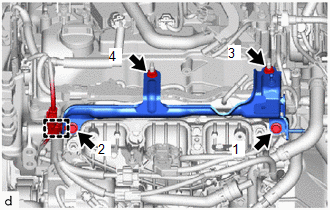
| (a) Temporarily install the fuel delivery guard. |
|
(b) Install the 2 bolts and 2 nuts in the order shown in the illustration.
Torque:
21 N·m {214 kgf·cm, 15 ft·lbf}
(c) Engage the engine wire clamp.
7. INSTALL OIL LEVEL GAUGE GUIDE
(a) Apply a light coat of engine oil to a new O-ring.
(b) Install the O-ring to the engine oil level guide.
(c) Install the engine oil level guide with the bolt.
Torque:
10 N·m {102 kgf·cm, 7 ft·lbf}
8. INSTALL OIL LEVEL GAUGE SUB-ASSEMBLY
(a) Install the engine oil level gauge sub-assembly.
9. INSTALL NO. 4 WATER BY-PASS PIPE
(a) Install the No. 4 water by-pass pipe to the cylinder head sub-assembly with the 3 bolts.
Torque:
10 N·m {102 kgf·cm, 7 ft·lbf}
10. CONNECT NO. 2 FUEL TUBE SUB-ASSEMBLY
(a) Connect the No. 2 fuel tube sub-assembly to the fuel delivery pipe.
Click here

11. INSTALL FUEL PIPE CLAMP
(a) Install the fuel pipe clamp to the fuel tube connector.
12. INSTALL ENGINE WIRE
Click here

13. INSTALL NO. 1 ENGINE COVER SUB-ASSEMBLY
Click here

14. INSPECT FOR FUEL LEAK
Click here

15. PERFORM INITIALIZATION
(a) Perform "Inspection After Repair" after replacing a fuel injector assembly.
Click here

 Inspection
INSPECTION PROCEDURE 1. INSPECT FUEL INJECTOR ASSEMBLY (a) Check the resistance. (1) Measure the resistance according to the value(s) in the table below...
Other information:
Toyota Yaris XP210 (2020-2026) Owner's Manual: Driver Air Bag
The driver’s air bag is mounted in the steering wheel. When air bag crash sensors detect a frontal impact of greater than moderate force, the driver’s air bag inflates quickly helping to reduce injury mainly to the driver’s head or chest caused by directly hitting the steering wheel...
Toyota Yaris XP210 (2020-2026) Reapir and Service Manual: New Key Registration Warning Message is not Displayed
DESCRIPTION If the new key registration warning message is not displayed after an electrical key transmitter sub-assembly has been registered, there may be communication problem between the certification ECU (smart key ECU assembly) and combination meter assembly (meter ECU)...
Categories
- Manuals Home
- Toyota Yaris Owners Manual
- Toyota Yaris Service Manual
- Engine & Hybrid System
- Diagnostic Trouble Code Chart
- Headlights
- New on site
- Most important about car
Key Suspend Function
If a key is left in the vehicle, the functions of the key left in the vehicle are temporarily suspended to prevent theft of the vehicle.
To restore the functions, press the unlock button on the functions-suspended key in the vehicle.


