Toyota Yaris: Air Fuel Ratio Sensor (for Sensor 1) / Removal
REMOVAL
CAUTION / NOTICE / HINT
The necessary procedures (adjustment, calibration, initialization, or registration) that must be performed after parts are removed, installed, or replaced during the air fuel ratio sensor removal/installation are shown below.
Necessary Procedure After Parts Removed/Installed/Replaced| Replacement Part or Procedure | Necessary Procedure | Effect/Inoperative when not Performed | Link |
|---|---|---|---|
| Inspection after repair |
|
|

CAUTION:
-
When the engine is hot, do not touch high-temperature areas such as the engine or exhaust manifold.
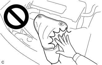
- Touching high-temperature areas such as the engine and exhaust manifold could result in burns.
PROCEDURE
1. REMOVE WINDSHIELD WIPER MOTOR AND LINK
Click here

2. REMOVE FRONT NO. 1 VENTILATOR SEAL
Click here

3. REMOVE WATER GUARD PLATE RH
Click here

4. REMOVE OUTER COWL TOP PANEL SUB-ASSEMBLY
Click here

5. SEPARATE NO. 1 AIR CLEANER HOSE
Click here

6. REMOVE INTAKE AIR RESONATOR
Click here

7. REMOVE AIR FUEL RATIO SENSOR
| (a) Disconnect the air fuel ratio sensor connector. |
|
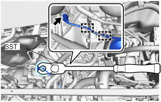
(b) Disengage the 2 clamps.
(c) Using SST, remove the air fuel ratio sensor from the exhaust manifold.
SST: 09224-00012
NOTICE:
If the air fuel ratio sensor has been struck or dropped, replace it.
 Components
COMPONENTS ILLUSTRATION
*1 WATER GUARD PLATE LH *2 NO. 1 FRONT VENTILATOR SEAL *3 OUTER COWL TOP PANEL SUB-ASSEMBLY - -
N*m (kgf*cm, ft...
 Inspection
INSPECTION PROCEDURE 1. INSPECT AIR FUEL RATIO SENSOR (a) Measure the resistance according to the value(s) in the table below. Standard Resistance: Tester Connection Condition Specified Condition D102-1(HA1A) - D102-2(+B) 20°C (68°F) 1...
Other information:
Toyota Yaris XP210 (2020-2026) Reapir and Service Manual: Precaution
PRECAUTION PRECAUTION FOR SEMICONDUCTOR POWER INTEGRATION ECU (a) Do not remove or install the semiconductor power integration ECU and power distribution box assembly with the negative (-) auxiliary battery terminal connected. NOTICE: After the ignition switch is turned off, there may be a waiting time before disconnecting the negative (-) auxiliary battery terminal...
Toyota Yaris XP210 (2020-2026) Reapir and Service Manual: Lost Communication with ECM/PCM "A" Missing Message (U010087,U010187,U012687,U012987,U013187,U015587)
DESCRIPTION When a communication malfunction is detected between the forward recognition camera and an ECU or sensor, a DTC is stored. DTC No. Detection Item DTC Detection Condition Trouble Area U010087 Lost Communication with ECM/PCM "A" Missing Message When the ignition switch is ON for 3 seconds or more, a communication malfunction between the forward recognition camera and the ECM continues for approximately 2 seconds or more...
Categories
- Manuals Home
- Toyota Yaris Owners Manual
- Toyota Yaris Service Manual
- Removal
- Fuse Panel Description
- Opening and Closing the Liftgate/Trunk Lid
- New on site
- Most important about car
Keys

To use the auxiliary key, press the knob and pull out the auxiliary key from the smart key.
