Toyota Yaris: Differential Case / Reassembly

Toyota Yaris XP210 (2020-2024) Reapir and Service Manual / Drivetrain / Ea67f (manual Transmission / Transaxle) / Differential Case / Reassembly

REASSEMBLY

PROCEDURE

1. INSTALL FRONT DIFFERENTIAL SIDE GEAR (w/o LSD)

(a) Coat the front differential side gear, front No. 1 differential side gear thrust washer and conical spring with gear oil.
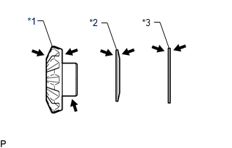
*1

Front Differential Side Gear

*2

Conical Spring

*3

Front No. 1 Differential Side Gear Thrust Washer

Gear Oil

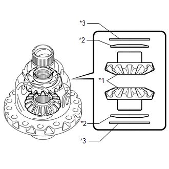
(b) Install the 2 front differential side gears, 2 front No. 1 differential side gear thrust washers and 2 conical springs to the front No. 1 differential case sub-assembly.

NOTICE:

  • Do not drop the front differential side gear, front No. 1 differential side gear thrust washer and conical spring.
  • Make sure that the conical spring is installed in the correct orientation.

*1

Front Differential Side Gear

*2

Conical Spring

*3

Front No. 1 Differential Side Gear Thrust Washer

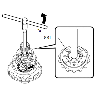
(c) Set SST as shown in the illustration and tighten it.
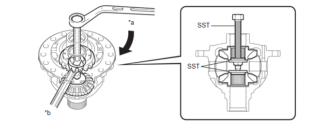
*a

Turn

*b

Hold

SST: 09528-52010

09528-05010

09953-05010

NOTICE:

Do not overtighten SST, as doing so will damage the front differential side gear, conical spring, front No. 1 differential side gear thrust washer and front No. 1 differential case sub-assembly.

HINT:

  • Tighten SST to create the necessary clearance to install the front differential pinions.
  • When installing the front differential pinions, do not overtighten SST, as it is necessary to rotate the front differential side gears.

(d) Coat the front differential pinion and front differential pinion thrust washer with gear oil.

Gear Oil

(e) Using SST as shown in the illustration, rotate the front differential side gear and install the 2 front differential pinions and 2 front differential pinion thrust washers.

SST: 09528-52010

09528-05030

CAUTION:

Be careful not to catch your fingers between the front differential pinion and front No. 1 differential case sub-assembly.

NOTICE:

Do not drop the front differential pinion and front differential pinion thrust washer.

*a

Turn

2. INSPECT FRONT DIFFERENTIAL PINION BACKLASH (w/o LSD)

Click here

3. INSTALL FRONT NO. 1 DIFFERENTIAL PINION SHAFT (w/o LSD)

(a) Coat a front No. 1 differential pinion shaft with gear oil.
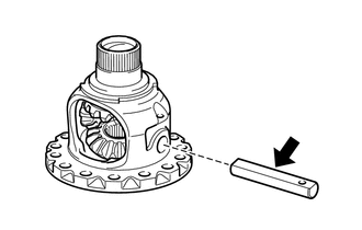
Gear Oil

(b) Install the front No. 1 differential pinion shaft to the front No. 1 differential case sub-assembly so that the hole for the front differential pinion shaft straight pin is aligned with the hole in the front No. 1 differential case sub-assembly.

4. INSPECT FRONT NO. 1 DIFFERENTIAL CASE SUB-ASSEMBLY (w/o LSD)

Click here

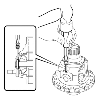
5. INSTALL FRONT DIFFERENTIAL PINION SHAFT STRAIGHT PIN (w/o LSD)

(a) Using a 5 mm pin punch and hammer, install the front differential pinion shaft straight pin to the front No. 1 differential case sub-assembly.

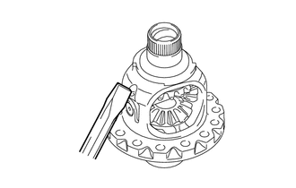
(b) Using a chisel and hammer, stake the front No. 1 differential case sub-assembly.

6. INSTALL FRONT DIFFERENTIAL RING GEAR

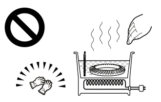
(a) Using a heater, heat the front differential ring gear to 90 to 100°C (194 to 212°F).

CAUTION:

Use thick gloves to protect your hands as the front differential ring gear is hot.

(b) Clean the contact surface of the front No. 1 differential case sub-assembly and front differential ring gear.

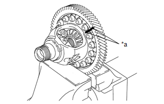
(c) While aligning the matchmarks, quickly install the front differential ring gear to the front No. 1 differential case sub-assembly with the 16 bolts.

Torque:

106 N·m {1081 kgf·cm, 78 ft·lbf}

*a

Matchmark

    Inspection

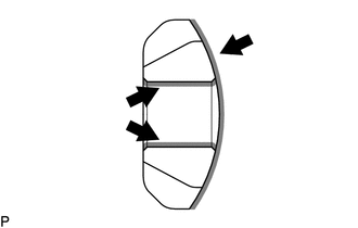
    INSPECTION PROCEDURE 1. INSPECT FRONT NO. 1 DIFFERENTIAL CASE SUB-ASSEMBLY (a) Using SST, rotate the front differential side gear as shown in the illustration...

    Differential Oil Seal (for Lh Side)

    ComponentsCOMPONENTS ILLUSTRATION *1 FRONT DRIVE SHAFT OIL SEAL LH - - ● Non-reusable part MP grease ReplacementREPLACEMENT CAUTION / NOTICE / HINT The necessary procedures (adjustment, calibration, initialization or registration) that must be performed after parts are removed and installed, or replaced during the front drive shaft oil seal LH removal/installation are shown below...

    Other information:

    Toyota Yaris XP210 (2020-2024) Owner's Manual: Fuel-Filler Lid and Cap


    WARNING When removing the fuel-filler cap, loosen the cap slightly and wait for any hissing to stop, then remove it Fuel spray is dangerous. Fuel can burn skin and eyes and cause illness if ingested. Fuel spray is released when there is pressure in the fuel tank and the fuel-filler cap is removed too quickly...

    Toyota Yaris XP210 (2020-2024) Reapir and Service Manual: Diagnostic Trouble Code Chart


    DIAGNOSTIC TROUBLE CODE CHART SFI System DTC No. Detection Item MIL Note Link P001013 A Camshaft Position Actuator Bank 1 Circuit Open Comes on SAE: P0010 P001100 Camshaft Position "A" - Timing Over-Advanced or System Performance Bank 1 Comes on SAE: P0011 P001200 Camshaft Position "A" - Timing Over-Retarded Bank 1 Comes on SAE: P0012 P001313 Camshaft Position "B" - Actuator Bank 1 Circuit Open Comes on SAE: P0013 P001400 Camshaft Position "B" - Timing Over-Advanced or System Performance Bank 1 Comes on SAE: P0014 P001500 Camshaft Position "B" - Timing Over-Retarded Bank 1 Comes on SAE: P0015 P001600 Crankshaft Position - Camshaft Position Correlation Bank 1 Sensor A Comes on SAE: P0016 P001700 Crankshaft Position - Camshaft Position Correlation Bank 1 Sensor B Comes on SAE: P0017 P003012 HO2S Heater Control Bank 1 Sensor 1 Circuit Short to Battery Comes on SAE: P0032 P003013 HO2S Heater Control Bank 1 Sensor 1 Circuit Open Comes on SAE: P0031 P003312 Turbocharger / Supercharger Bypass Valve "A" Control Circuit Short to Battery - SAE: P0035 P003314 Turbocharger / Supercharger Bypass Valve "A" Control Circuit Short to Ground or Open - SAE: P0034 P003612 HO2S Heater Control Circuit Bank 1 Sensor 2 Circuit Short to Battery Comes on SAE: P0038 P003613 A/F (O2) Heater Control Circuit Bank 1 Sensor 2 Circuit Open Comes on SAE: P0037 P006D62 Barometric Pressure - Turbocharger/Supercharger Inlet Pressure Correlation Bank 1 Signal Compare Failure - SAE: P006D P007A11 Charge Air Cooler Temperature Sensor Bank 1 Circuit Short to Ground - SAE: P007C P007A15 Charge Air Cooler Temperature Sensor Bank 1 Circuit Short to Battery or Open - SAE: P007D P008700 Fuel Rail / System Pressure - Too Low Comes on SAE: P0087 P008800 Fuel Rail / System Pressure - Too High Comes on SAE: P0088 P008A00 Low Pressure Fuel System Pressure - Too Low - SAE: P008A P008B00 Low Pressure Fuel System Pressure - Too High - SAE: P008B P00CF62 Barometric Pressure - Turbocharger / Supercharger Boost Sensor "A" Signal Compare Failure Comes on SAE: P00CF P010012 Mass or Volume Air Flow Sensor "A" Circuit Short to Battery Comes on SAE: P0103 P010014 Mass or Volume Air Flow Sensor "A" Circuit Short to Ground or Open Comes on SAE: P0102 P010511 Manifold Absolute Pressure / Barometric Pressure Sensor Circuit Short to Ground Comes on SAE: P0107 P010515 Manifold Absolute Pressure / Barometric Pressure Sensor Circuit Short to Battery or Open Comes on SAE: P0108 P011011 Intake Air Temperature Sensor 1 Bank 1 Circuit Short to Ground Comes on SAE: P0112 P011015 Intake Air Temperature Sensor 1 Bank 1 Circuit Short to Battery or Open Comes on SAE: P0113 P011511 Engine Coolant Temperature Sensor 1 Circuit Short to Ground Comes on SAE: P0117 P011515 Engine Coolant Temperature Sensor 1 Circuit Short to Battery or Open Comes on SAE: P0118 P01152A Engine Coolant Temperature Sensor 1 Signal Stuck in Range Comes on SAE: P0116 P012011 Throttle / Pedal Position Sensor / Switch "A" Circuit Short to Ground Comes on SAE: P0122 P012015 Throttle / Pedal Position Sensor / Switch "A" Circuit Short to Battery or Open Comes on SAE: P0123 P01201C Throttle / Pedal Position Sensor / Switch "A" Circuit Voltage Out of Range Comes on SAE: P0121 P012A11 Turbocharger/Supercharger Inlet Pressure Sensor "A" Circuit Low Circuit Short to Ground - SAE: P012C P012A15 Turbocharger/Supercharger Inlet Pressure Sensor "A" Circuit High Circuit Short to Battery or Open - SAE: P012D P013616 A/F (O2) Sensor Circuit Bank 1 Sensor 2 Circuit Current (Voltage) Below Threshold Comes on SAE: P0136 P017100 System Too Lean Bank 1 Comes on SAE: P0171 P017200 System Too Rich Bank 1 Comes on SAE: P0172 P019011 Fuel Rail Pressure Sensor "A" Circuit Short to Ground Comes on SAE: P0192 P019015 Fuel Rail Pressure Sensor "A" Circuit Short to Battery or Open Comes on SAE: P0193 P019511 Engine Oil Temperature Sensor Circuit Short to Ground - SAE: P0197 P019515 Engine Oil Temperature Sensor Circuit Short to Battery or Open - SAE: P0198 P020113 Cylinder 1 Injector "A" Circuit Open Comes on SAE: P0201 P020213 Cylinder 2 Injector "A" Circuit Open Comes on SAE: P0202 P020313 Cylinder 3 Injector "A" Circuit Open Comes on SAE: P0203 P022011 Throttle/Pedal Position Sensor/Switch "B" Circuit Short to Ground Comes on SAE: P0222 P022015 Throttle/Pedal Position Sensor/Switch "B" Circuit Short to Battery or Open Comes on SAE: P0223 P023400 Turbocharger/Supercharger "A" Overboost Condition - SAE: P0234 P023511 Turbocharger/Supercharger Boost Sensor "A" Circuit Short to Ground Comes on SAE: P0237 P023515 Turbocharger/Supercharger Boost Sensor "A" Circuit Short to Battery or Open Comes on SAE: P0238 P02351C Turbocharger/Supercharger Boost Sensor "A" Circuit Voltage Out of Range - SAE: P0236 P024313 Turbocharger/Supercharger Wastegate Solenoid "A" Circuit Open Does not come on SAE: P0243 P030000 Random/Multiple Cylinder Misfire Detected Comes on/Blinks* *: The MIL flashes when a catalyst-damaging misfire is detected...

    Categories

    Key Suspend Function

    If a key is left in the vehicle, the functions of the key left in the vehicle are temporarily suspended to prevent theft of the vehicle.

    To restore the functions, press the unlock button on the functions-suspended key in the vehicle.

    read more

     
    Copyright © 2024 www.toyaris4.com