Toyota Yaris: Windshield Outside Moulding / Installation
INSTALLATION
CAUTION / NOTICE / HINT
HINT:
- Use the same procedure for the RH side and LH side.
- The following procedure is for the LH side.
PROCEDURE
1. INSTALL NO. 4 WINDSHIELD OUTSIDE MOULDING CLIP
HINT:
Perform the following procedure only when replacement of a No. 4 windshield outside moulding clip is necessary.
(a) Using a riveter with a nose piece, install 5 new No. 4 windshield outside moulding clips.
HINT:
If the mandrel of the No. 4 windshield outside moulding clip does not come off on the first operation of the rivet gun, slide the rivet gun forward on the mandrel and operate it again.
NOTICE:
- Do not pry the No. 4 windshield outside moulding clip with the riveter, as this will cause damage to the riveter and mandrel.
-
Confirm that the No. 4 windshield outside moulding clips are seated properly against the vehicle body.
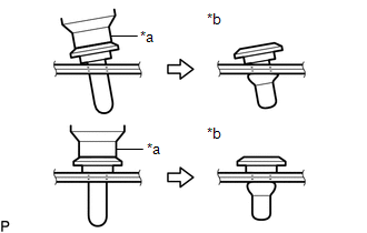
*a
Riveter
*b
Incorrect
- Do not tilt the riveter when installing the No. 4 windshield outside moulding clip to the vehicle body.
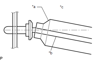
| *a | Riveter |
| *b | Mandrel |
| *c | Incorrect |
(b) Install the windshield glass sub-assembly.
Click here
.gif)
2. INSTALL NO. 1 WINDSHIELD OUTSIDE MOULDING CLIP
HINT:
Perform the following procedure only when replacement of a No. 1 windshield outside moulding clip is necessary.
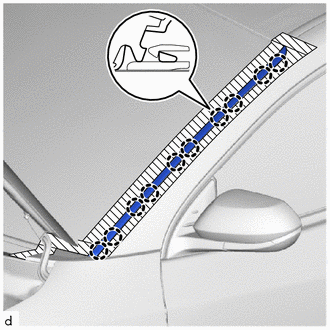
(a) Engage the claws to install 5 new No. 1 windshield outside moulding clips as shown in the illustration.
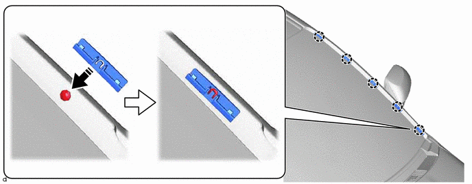
.png) | Install in this Direction | - | - |
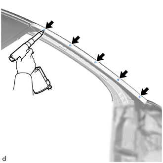
3. INSTALL WINDSHIELD OUTSIDE MOULDING
| (a) Engage the claws to install the windshield outside moulding. |
|
(b) Remove the protective tape.
 Removal
REMOVAL CAUTION / NOTICE / HINT HINT:
Use the same procedure for the RH side and LH side.
The following procedure is for the LH side.
PROCEDURE 1...
 Horn
Horn
..
Other information:
Toyota Yaris XP210 (2020-2026) Reapir and Service Manual: Turbocharger/Supercharger Inlet Pressure Sensor "A" Circuit High Circuit Short to Battery or Open (P012A15)
DESCRIPTION Refer to DTC P012A11. Click here DTC No. Detection Item DTC Detection Condition Trouble Area MIL Note P012A15 Turbocharger/Supercharger Inlet Pressure Sensor "A" Circuit High Circuit Short to Battery or Open The output voltage from the E...
Toyota Yaris XP210 (2020-2026) Reapir and Service Manual: Customize Parameters
CUSTOMIZE PARAMETERS CUSTOMIZE LIGHTING SYSTEM (INT) NOTICE: When the customer requests a change in a function, first make sure that the function can be customized. Be sure to make a note of the current settings before customizing. When troubleshooting a function, first make sure that the function is set to the default setting...
Categories
- Manuals Home
- Toyota Yaris Owners Manual
- Toyota Yaris Service Manual
- Battery Monitor Module General Electrical Failure (P058A01)
- Power Integration No.1 System Missing Message (B235287,B235587,B235787-B235987)
- Fuse Panel Description
- New on site
- Most important about car
Front Seat Belt Pretensioners
The front seat belt pretensioners are designed to deploy in moderate or severe frontal, near frontal collisions.
In addition, the pretensioners operate when a side collision or a rollover accident is detected. The pretensioners operate differently depending on what types of air bags are equipped. For more details about the seat belt pretensioner operation, refer to the SRS Air Bag Deployment Criteria.