Toyota Yaris: Sfi System / Turbocharger/Supercharger Boost Sensor "A" Circuit Voltage Out of Range (P02351C)
DESCRIPTION
Refer to DTC P023511.
Click here

| DTC No. | Detection Item | DTC Detection Condition | Trouble Area | MIL | Note |
|---|---|---|---|---|---|
| P02351C | Turbocharger/Supercharger Boost Sensor "A" Circuit Voltage Out of Range | The discrepancy between the air volume estimated from the No. 1 turbo pressure sensor and the mass air flow meter output value equals or exceeds the threshold value. |
| - | SAE: P0236 |
MONITOR DESCRIPTION
If the discrepancy between the air volume estimated from the No. 1 turbo pressure sensor and the mass air flow meter output value equals or exceeds the threshold value, the ECM stores a DTC.
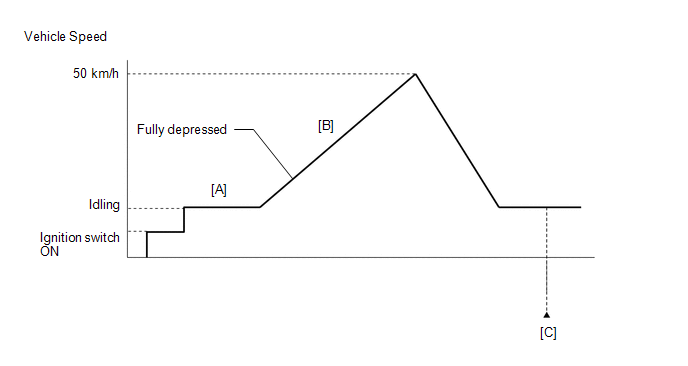
CONFIRMATION DRIVING PATTERN
- Connect the GTS to the DLC3.
- Turn the ignition switch to ON and turn the GTS on.
- Clear the DTCs (even if no DTCs are stored, perform the clear DTC procedure).
- Turn the ignition switch off and wait for at least 30 seconds.
- Turn the ignition switch to ON and turn the GTS on.
- Start the engine and warm it up until the engine coolant temperature reaches 75°C (167°F) or higher [A].
-
Accelerate to 50 km/h (31 mph) or more with the accelerator pedal fully depressed [B].
CAUTION:
When performing the confirmation driving pattern, obey all speed limits and traffic laws.
- Enter the following menus: Powertrain / Engine / Trouble Codes [C].
-
Read the pending DTCs.
HINT:
- If a pending DTC is output, the system is malfunctioning.
- If a pending DTC is not output, perform the following procedure.
- Enter the following menus: Powertrain / Engine / Utility / All Readiness.
- Input the DTC: P02351C.
-
Check the DTC judgment result.
GTS Display
Description
NORMAL
- DTC judgment completed
- System normal
ABNORMAL
- DTC judgment completed
- System abnormal
INCOMPLETE
- DTC judgment not completed
- Perform driving pattern after confirming DTC enabling conditions
HINT:
- If the judgment result shows NORMAL, the system is normal.
- If the judgment result shows ABNORMAL, the system has a malfunction.
- If the judgment result shows INCOMPLETE, perform steps [B] and [C] again.
WIRING DIAGRAM
Refer to DTC P010012 for the mass air flow meter sub-assembly circuit.
Click here

Refer to DTC P10D311 for intake air temperature sensor (No. 1 turbo pressure sensor) circuit.
Click here

Refer to DTC P023511 for No. 2 turbo pressure sensor circuit.
Click here

Refer to DTC P012A11 for the E.F.I. vacuum sensor assembly circuit.
Click here

CAUTION / NOTICE / HINT
HINT:
Read Freeze Frame Data using the GTS. The ECM records vehicle and driving condition information as Freeze Frame Data the moment a DTC is stored. When troubleshooting, Freeze Frame Data can help determine if the vehicle was moving or stationary, if the engine was warmed up or not, if the air fuel ratio was lean or rich, and other data from the time the malfunction occurred.
PROCEDURE
| 1. | CHECK ANY OTHER DTCS OUTPUT (IN ADDITION TO DTC P02351C) |
(a) Read the DTCs.
Powertrain > Engine > Trouble Codes| Result | Proceed to |
|---|---|
| P02351C is output | A |
| P02351C and other DTCs are output | B |
HINT:
If any DTCs other than P02351C are output, troubleshoot those DTCs first.
| B |
 | GO TO DTC CHART |
|

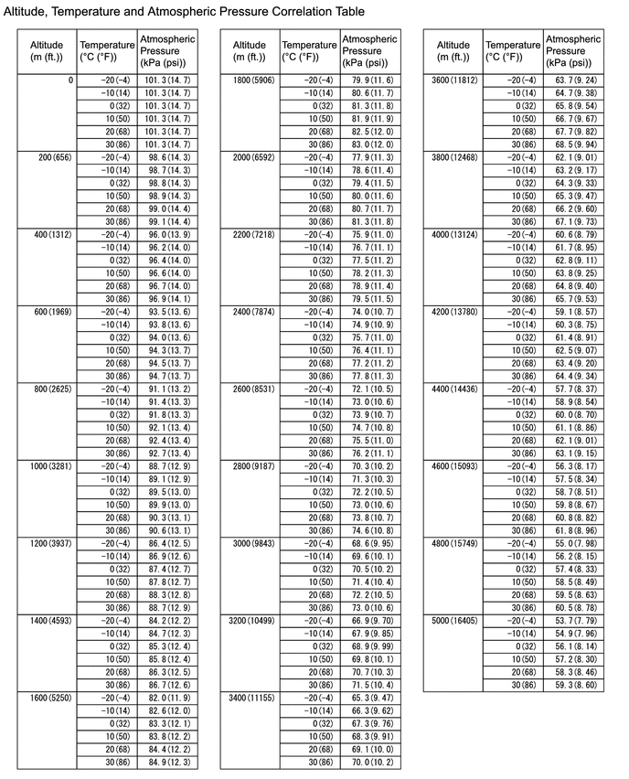
| 2. | READ VALUE USING GTS (ATMOSPHERIC PRESSURE) |
(a) Enter the following menus.
Powertrain > Engine > Data List| Tester Display |
|---|
| Atmospheric Pressure |
(b) Using the table, read the normal atmospheric pressure value for the applicable altitude and temperature.
HINT:
- Standard atmospheric pressure is approximately 101 kPa(abs) (15 psi(abs)).
- For every 100 m (328 ft.) increase in altitude, atmospheric pressure drops by approximately 1 kPa (0.15 psi). This varies by weather.
(c) Compare the Atmospheric pressure value in the Data List with the normal atmospheric value from the table.
| Result | Proceed to |
|---|---|
| Other than the following | A |
| Difference between Atmospheric Pressure in the Data List and normal atmospheric pressure value is 10 kPa (1.45 psi) or more. | B |
| B |
 | REPLACE ECM |
|

| 3. | READ VALUE USING GTS (INTAKE AIR TEMPERATURE B1S1 (TURBO)) |
(a) Remove the No. 1 turbo pressure sensor.
HINT:
Do not disconnect the connector.
(b) Enter the following menus.
Powertrain > Engine > Data List| Tester Display |
|---|
| Intake Air Temperature B1S1 (Turbo) |
(c) Read the value displayed on the GTS.
| Result | Proceed to |
|---|---|
| Other than the following | A |
| Difference between Intake Air Temperature B1S1 (Turbo) in the Data List and actual outside air temperature value is 10°C (18°F) or more. | B |
| B |
 | GO TO STEP 19 |
|

| 4. | INSPECT MASS AIR FLOW METER SUB-ASSEMBLY |
Click here

| NG |
 | GO TO STEP 17 |
|

| 5. | INSPECT NO. 2 TURBO PRESSURE SENSOR |
Click here

| NG |
 | GO TO STEP 15 |
|

| 6. | INSPECT E.F.I. VACUUM SENSOR ASSEMBLY |
Click here

| NG |
 | GO TO STEP 13 |
|

| 7. | CHECK INTAKE SYSTEM |
(a) Check that there is no air suction or blockage at any points in the intake system.
Click here

OK:
No air suction or blockage.
HINT:
Perform "Inspection After Repair" after repairing or replacing the intake system.
Click here

| NG |
 | REPAIR OR REPLACE INTAKE SYSTEM |
|

| 8. | CLEAR DTC |
(a) Clear the DTCs.
Powertrain > Engine > Clear DTCs(b) Turn the ignition switch off and wait for at least 30 seconds.
|

| 9. | CHECK WHETHER DTC OUTPUT RECURS (DTC P02351C) |
(a) Drive the vehicle in accordance with the driving pattern described in Confirmation Driving Pattern.
(b) Enter the following menus.
Powertrain > Engine > Utility| Tester Display |
|---|
| All Readiness |
(c) Input the DTC: P02351C.
(d) Check the DTC judgment result.
| Result | Proceed to |
|---|---|
| NORMAL (DTCs are not output) | A |
| ABNORMAL (P02351C is output) | B |
| A |
 | END |
|

| 10. | REPLACE NO. 1 TURBO PRESSURE SENSOR |
Click here

|

| 11. | CLEAR DTC |
(a) Clear the DTCs.
Powertrain > Engine > Clear DTCs(b) Turn the ignition switch off and wait for at least 30 seconds.
|

| 12. | CHECK WHETHER DTC OUTPUT RECURS (DTC P02351C) |
(a) Drive the vehicle in accordance with the driving pattern described in Confirmation Driving Pattern.
(b) Enter the following menus.
Powertrain > Engine > Utility| Tester Display |
|---|
| All Readiness |
(c) Input the DTC: P02351C.
(d) Check the DTC judgment result.
| Result | Proceed to |
|---|---|
| NORMAL (DTCs are not output) | A |
| ABNORMAL (P02351C is output) | B |
| A |
 | END |
| B |
 | REPLACE ECM |
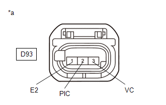
| 13. | CHECK HARNESS AND CONNECTOR |
(a) Disconnect the E.F.I. vacuum sensor assembly connector.
(b) Turn the ignition switch to ON.
| (c) Measure the voltage according to the value(s) in the table below. Standard Voltage:
|
|
(d) Turn the ignition switch off and wait for at least 30 seconds.
(e) Measure the resistance according to the value(s) in the table below.
Standard Resistance:
| Tester Connection | Condition | Specified Condition |
|---|---|---|
| D93-3(VC) - D93-2(PIC) | Ignition switch off | 171 to 189 kΩ |
| D93-1(E2) - Body ground | Always | Below 1 Ω |
| OK |
 | REPLACE E.F.I. VACUUM SENSOR ASSEMBLY |
|

| 14. | CHECK HARNESS AND CONNECTOR (E.F.I. VACUUM SENSOR ASSEMBLY - ECM) |
(a) Disconnect the E.F.I. vacuum sensor assembly connector.
(b) Disconnect the ECM connector.
(c) Measure the resistance according to the value(s) in the table below.
Standard Resistance:
| Tester Connection | Condition | Specified Condition |
|---|---|---|
| D93-3(VC) - D104-82(VCPC) | Always | Below 1 Ω |
| D93-2(PIC) - D104-105(PIC) | Always | Below 1 Ω |
| D93-1(E2) - D104-81(EPIC) | Always | Below 1 Ω |
| D93-3(VC) or D104-82(VCPC) - Body ground and other terminals | Always | 10 kΩ or higher |
| D93-2(PIC) or D104-105(PIC) - Body ground and other terminals | Always | 10 kΩ or higher |
| OK |
 | REPLACE ECM |
| NG |
 | REPAIR OR REPLACE HARNESS OR CONNECTOR |
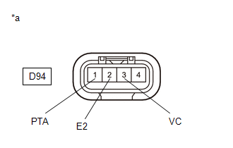
| 15. | CHECK HARNESS AND CONNECTOR |
(a) Disconnect the No. 2 turbo pressure sensor connector.
(b) Turn the ignition switch to ON.
| (c) Measure the voltage according to the value(s) in the table below. Standard Voltage:
|
|
(d) Turn the ignition switch off and wait for at least 30 seconds.
(e) Measure the resistance according to the value(s) in the table below.
Standard Resistance:
| Tester Connection | Condition | Specified Condition |
|---|---|---|
| D94-3(VC) - D94-1(PTA) | Ignition switch off | 171 to 189 kΩ |
| D94-2(E2) - Body ground | Always | Below 1 Ω |
| OK |
 | REPLACE NO. 2 TURBO PRESSURE SENSOR |
|

| 16. | CHECK HARNESS AND CONNECTOR (NO. 2 TURBO PRESSURE SENSOR - ECM) |
(a) Disconnect the No. 2 turbo pressure sensor connector.
(b) Disconnect the ECM connector.
(c) Measure the resistance according to the value(s) in the table below.
Standard Resistance:
| Tester Connection | Condition | Specified Condition |
|---|---|---|
| D94-3(VC) - D104-80(VPTA) | Always | Below 1 Ω |
| D94-1(PTA) - D104-103(PTA) | Always | Below 1 Ω |
| D94-2(E2) - D104-79(EPTA) | Always | Below 1 Ω |
| D94-3(VC) or D104-80(VPTA) - Body ground and other terminals | Always | 10 kΩ or higher |
| D94-1(PTA) or D104-103(PTA) - Body ground and other terminals | Always | 10 kΩ or higher |
| OK |
 | REPLACE ECM |
| NG |
 | REPAIR OR REPLACE HARNESS OR CONNECTOR |
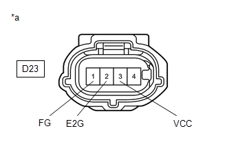
| 17. | CHECK HARNESS AND CONNECTOR |
(a) Disconnect the mass air flow meter sub-assembly connector.
(b) Turn the ignition switch to ON.
| (c) Measure the voltage according to the value(s) in the table below. Standard Voltage:
|
|
(d) Turn the ignition switch off and wait for at least 30 seconds.
(e) Measure the resistance according to the value(s) in the table below.
Standard Resistance:
| Tester Connection | Condition | Specified Condition |
|---|---|---|
| D23-3(VCC) - D23-1(FG) | Ignition switch off | 2.09 to 2.31 kΩ |
| D23-2(E2G) - Body ground | Always | Below 1 Ω |
HINT:
Perform "Inspection After Repair" after replacing the mass air flow meter sub-assembly.
Click here

| OK |
 | REPLACE MASS AIR FLOW METER SUB-ASSEMBLY |
|

| 18. | CHECK HARNESS AND CONNECTOR (MASS AIR FLOW METER SUB-ASSEMBLY - ECM) |
(a) Disconnect the mass air flow meter sub-assembly connector.
(b) Disconnect the ECM connector.
(c) Measure the resistance according to the value(s) in the table below.
Standard Resistance:
| Tester Connection | Condition | Specified Condition |
|---|---|---|
| D23-3(VCC) - D104-84(VCVG) | Always | Below 1 Ω |
| D23-1(FG) - D104-107(VG) | Always | Below 1 Ω |
| D23-2(E2G) - D104-83(E2G) | Always | Below 1 Ω |
| D23-3(VCC) or D104-84(VCVG) - Body ground and other terminals | Always | 10 kΩ or higher |
| D23-1(FG) or D104-107(VG) - Body ground and other terminals | Always | 10 kΩ or higher |
| OK |
 | REPLACE ECM |
| NG |
 | REPAIR OR REPLACE HARNESS OR CONNECTOR |
| 19. | INSPECT NO. 1 TURBO PRESSURE SENSOR (INTAKE AIR TEMPERATURE SENSOR) |
Click here

| NG |
 | REPLACE NO. 1 TURBO PRESSURE SENSOR |
|

| 20. | CHECK HARNESS AND CONNECTOR (NO. 1 TURBO PRESSURE SENSOR - ECM) |
(a) Disconnect the No. 1 turbo pressure sensor connector.
(b) Disconnect the ECM connector.
(c) Measure the resistance according to the value(s) in the table below.
Standard Resistance:
| Tester Connection | Condition | Specified Condition |
|---|---|---|
| D95-4(THIM) - D104-99(THIM) | Always | Below 1 Ω |
| D95-2(E2) - D104-76(EPIM) | Always | Below 1 Ω |
| D95-4(THIM) or D104-99(THIM) - Body ground and other terminals | Always | 10 kΩ or higher |
| OK |
 | REPLACE ECM |
| NG |
 | REPAIR OR REPLACE HARNESS OR CONNECTOR |
 Turbocharger/Supercharger Boost Sensor "A" Circuit Short to Ground (P023511)
DESCRIPTION The internal sensor in the No. 2 turbo pressure sensor detects the air outlet duct internal pressure as a voltage.
DTC No. Detection Item DTC Detection Condition Trouble Area MIL Note P023511 Turbocharger/Supercharger Boost Sensor "A" Circuit Short to Ground The output voltage from the No...
 Turbocharger/Supercharger Wastegate Solenoid "A" Circuit Open (P024313)
DESCRIPTION The waste gate valve is built into the turbine housing and is operated by the vacuum regulating valve assembly. The ECM uses duty control to open and close the vacuum regulating valve assembly...
Other information:
Toyota Yaris XP210 (2020-2025) Reapir and Service Manual: Multi-axis Acceleration Sensor Module "A" Supply Voltage Circuit Voltage Out of Range (C14D71C)
DESCRIPTION The airbag sensor assembly has a built-in yaw rate and acceleration sensor and detects the vehicle condition. This DTC is stored when the skid control ECU (brake actuator assembly) receives a sensor supply voltage malfunction signal from the acceleration sensor (airbag sensor assembly)...
Toyota Yaris XP210 (2020-2025) Reapir and Service Manual: Reassembly
REASSEMBLY PROCEDURE 1. INSTALL CLEAN AIR FILTER (a) Install the clean air filter. NOTICE: Make sure that the "UP" mark is facing the correct direction before installing the clean air filter. 2. INSTALL AIR FILTER COVER PLATE (a) Engage the guides and claw to install the air filter cover plate...
Categories
- Manuals Home
- Toyota Yaris Owners Manual
- Toyota Yaris Service Manual
- Opening and Closing the Liftgate/Trunk Lid
- G16e-gts (engine Mechanical)
- Fuse Panel Description
- New on site
- Most important about car
Keys

To use the auxiliary key, press the knob and pull out the auxiliary key from the smart key.
