Toyota Yaris: Sfi System / Turbocharger/Supercharger Boost Sensor "A" Circuit Short to Ground (P023511)
DESCRIPTION
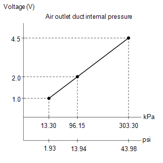
The internal sensor in the No. 2 turbo pressure sensor detects the air outlet duct internal pressure as a voltage.
| DTC No. | Detection Item | DTC Detection Condition | Trouble Area | MIL | Note |
|---|---|---|---|---|---|
| P023511 | Turbocharger/Supercharger Boost Sensor "A" Circuit Short to Ground | The output voltage from the No. 2 turbo pressure sensor is below 0.97 V for 3 seconds or more (1 trip detection logic). |
| Comes on | SAE: P0237 |
HINT:
When a DTC is output, check the Data List item "Boost Pressure Sensor" using the GTS.
Click here

| DTC No. | Boost Pressure Sensor | Malfunction |
|---|---|---|
| P023511 | Approximately 0 kPa [0 psi] |
|
If the Data List displays a normal value, the normal value may be due to a temporary recovery from the malfunction condition. Check for intermittent problems.
MONITOR DESCRIPTION
The ECM calculates the air outlet duct internal pressure from the No.2 turbo pressure sensor output voltage. If the No. 2 turbo pressure sensor output voltage is not within the normal range, there may be a malfunction in the No. 2 turbo pressure sensor or an open or short circuit. In this case, the ECM illuminates the MIL and stores a DTC.
Example:
When the sensor output voltage is below 0.97 V for 3 seconds or more, the ECM stores a DTC.
MONITOR STRATEGY
| Required Sensors/Components | No. 2 turbo pressure sensor |
| Frequency of Operation | Continuous |
CONFIRMATION DRIVING PATTERN
- Connect the GTS to the DLC3.
- Turn the ignition switch to ON and turn the GTS on.
- Clear the DTCs (even if no DTCs are stored, perform the clear DTC procedure).
- Turn the ignition switch off and wait for at least 30 seconds.
- Turn the ignition switch to ON.
- Turn the GTS on.
- Start the engine and wait 5 seconds or more.
- Enter the following menus: Powertrain / Engine / Trouble Codes.
-
Read the pending DTCs.
HINT:
- If a pending DTC is output, the system is malfunctioning.
- If a pending DTC is not output, perform the following procedure.
- Enter the following menus: Powertrain / Engine / Utility / All Readiness.
- Input the DTC: P023511.
-
Check the DTC judgment result.
GTS Display
Description
NORMAL
- DTC judgment completed
- System normal
ABNORMAL
- DTC judgment completed
- System abnormal
INCOMPLETE
- DTC judgment not completed
- Perform driving pattern after confirming DTC enabling conditions
HINT:
- If the judgment result shows NORMAL, the system is normal.
- If the judgment result shows ABNORMAL, the system has a malfunction.
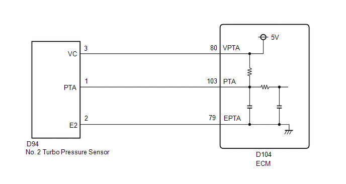
WIRING DIAGRAM
CAUTION / NOTICE / HINT
HINT:
Read Freeze Frame Data using the GTS. The ECM records vehicle and driving condition information as Freeze Frame Data the moment a DTC is stored. When troubleshooting, Freeze Frame Data can help determine if the vehicle was moving or stationary, if the engine was warmed up or not, if the air fuel ratio was lean or rich, and other data from the time the malfunction occurred.
PROCEDURE
| 1. | CHECK HARNESS AND CONNECTOR |
HINT:
Make sure that the connector is properly connected. If it is not, securely connect it and check for DTCs again.
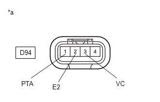
(a) Disconnect the No. 2 turbo pressure sensor connector.
(b) Turn the ignition switch to ON.
| (c) Measure the voltage according to the value(s) in the table below. Standard Voltage:
|
|
(d) Turn the ignition switch off and wait for at least 30 seconds.
(e) Measure the resistance according to the value(s) in the table below.
Standard Resistance:
| Tester Connection | Condition | Specified Condition |
|---|---|---|
| D94-3(VC) - D94-1(PTA) | Ignition switch off | 171 to 189 kΩ |
| OK |
 | REPLACE NO. 2 TURBO PRESSURE SENSOR |
|

| 2. | CHECK HARNESS AND CONNECTOR (NO. 2 TURBO PRESSURE SENSOR - ECM) |
(a) Disconnect the No. 2 turbo pressure sensor connector.
(b) Disconnect the ECM connector.
(c) Measure the resistance according to the value(s) in the table below.
Standard Resistance:
| Tester Connection | Condition | Specified Condition |
|---|---|---|
| D94-3(VC) - D104-80(VPTA) | Always | Below 1 Ω |
| D94-3(VC) or D104-80(VPTA) - Body ground and other terminals | Always | 10 kΩ or higher |
| OK |
 | REPLACE ECM |
| NG |
 | REPAIR OR REPLACE HARNESS OR CONNECTOR |
 Turbocharger/Supercharger "A" Overboost Condition (P023400)
DESCRIPTION Refer to DTC P003312. Click here
DTC No. Detection Item DTC Detection Condition Trouble Area MIL Note P023400 Turbocharger/Supercharger "A" Overboost Condition Boost pressure exceeds the threshold value (calculated from turbocharger speed upper limit value)...
 Turbocharger/Supercharger Boost Sensor "A" Circuit Voltage Out of Range (P02351C)
DESCRIPTION Refer to DTC P023511. Click here
DTC No. Detection Item DTC Detection Condition Trouble Area MIL Note P02351C Turbocharger/Supercharger Boost Sensor "A" Circuit Voltage Out of Range The discrepancy between the air volume estimated from the No...
Other information:
Toyota Yaris XP210 (2020-2025) Reapir and Service Manual: Camshaft Position Sensor "A" Bank 1 or Single Sensor Circuit Short to Ground (P034011,P034015)
DESCRIPTION The camshaft position sensor (for intake camshaft) (VV1 signal) consists of a magnet and MRE (Magneto-Resistive Element). The intake camshaft has a timing rotor for the camshaft position sensor. When the intake camshaft rotates, changes occur in the air gaps between the timing rotor and MRE, which affects the magnetic field...
Toyota Yaris XP210 (2020-2025) Reapir and Service Manual: Parts Location
PARTS LOCATION ILLUSTRATION *1 BRAKE MASTER CYLINDER RESERVOIR ASSEMBLY - BRAKE FLUID LEVEL WARNING SWITCH *2 THERMISTOR ASSEMBLY *3 ECM *4 BRAKE ACTUATOR ASSEMBLY - SKID CONTROL ECU ILLUSTRATION *1 HEADLIGHT ASSEMBLY RH *2 HEADLIGHT ASSEMBLY LH *3 HEADLIGHT UNIT ASSEMBLY RH *4 HEADLIGHT UNIT ASSEMBLY LH *5 HEADLIGHT CORD *6 OUTER REAR VIEW MIRROR ASSEMBLY RH - SIDE TURN SIGNAL LIGHT ASSEMBLY RH *7 OUTER REAR VIEW MIRROR ASSEMBLY LH - SIDE TURN SIGNAL LIGHT ASSEMBLY LH *8 REAR COMBINATION LIGHT ASSEMBLY RH *9 REAR COMBINATION LIGHT ASSEMBLY LH *10 REAR TURN SIGNAL LIGHT LED ILLUSTRATION *1 MAIN BODY ECU (MULTIPLEX NETWORK BODY ECU) *2 POWER DISTRIBUTION BOX ASSEMBLY - ECU-DCC NO...
Categories
- Manuals Home
- Toyota Yaris Owners Manual
- Toyota Yaris Service Manual
- To Set Speed
- Auto Lock/Unlock Function
- Power Integration No.1 System Missing Message (B235287,B235587,B235787-B235987)
- New on site
- Most important about car
Front Seat Belt Pretensioners
The front seat belt pretensioners are designed to deploy in moderate or severe frontal, near frontal collisions.
In addition, the pretensioners operate when a side collision or a rollover accident is detected. The pretensioners operate differently depending on what types of air bags are equipped. For more details about the seat belt pretensioner operation, refer to the SRS Air Bag Deployment Criteria.