Toyota Yaris: Sfi System / Turbocharger/Supercharger "A" Overboost Condition (P023400)
DESCRIPTION
Refer to DTC P003312.
Click here

| DTC No. | Detection Item | DTC Detection Condition | Trouble Area | MIL | Note |
|---|---|---|---|---|---|
| P023400 | Turbocharger/Supercharger "A" Overboost Condition | Boost pressure exceeds the threshold value (calculated from turbocharger speed upper limit value). (1 trip detection logic) |
| - | SAE: P0234 |
MONITOR DESCRIPTION
If the boost pressure exceeds the threshold value (calculated from turbocharger speed upper limit value or compressor downstream temperature upper limit value), there may be a turbocharger system malfunction. In this case, the ECM stores a DTC.
CONFIRMATION DRIVING PATTERN
- Connect the GTS to the DLC3.
- Turn the ignition switch to ON and turn the GTS on.
- Clear the DTCs (even if no DTCs are stored, perform the clear DTC procedure).
- Turn the ignition switch off and wait for at least 30 seconds.
- Turn the ignition switch to ON and turn the GTS on.
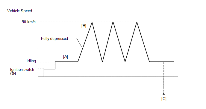
- Start the engine and warm it up until the engine coolant temperature reaches 75°C (167°F) or higher [A].
-
Accelerate to 50 km/h (31 mph) or more with the accelerator pedal fully depressed [B].
CAUTION:
When performing the confirmation driving pattern, obey all speed limits and traffic laws.
- Enter the following menus: Powertrain / Engine / Trouble Codes [C].
-
Read the pending DTCs.
HINT:
- If a pending DTC is output, the system is malfunctioning.
- If a pending DTC is not output, perform the following procedure.
- Enter the following menus: Powertrain / Engine / Utility / All Readiness.
- Input the DTC: P023400.
-
Check the DTC judgment result.
GTS Display
Description
NORMAL
- DTC judgment completed
- System normal
ABNORMAL
- DTC judgment completed
- System abnormal
INCOMPLETE
- DTC judgment not completed
- Perform driving pattern after confirming DTC enabling conditions
HINT:
- If the judgment result shows NORMAL, the system is normal.
- If the judgment result shows ABNORMAL, the system has a malfunction.
- If the judgment result shows INCOMPLETE, perform steps [B] and [C] again.
WIRING DIAGRAM
Refer to DTC P010012 for the mass air flow meter sub-assembly circuit.
Click here

Refer to DTC P010012 for intake air temperature sensor (mass air flow meter sub-assembly) circuit.
Click here

Refer to DTC P012A11 for the E.F.I. vacuum sensor assembly circuit.
Click here

Refer to DTC P023511 for No. 2 turbo pressure sensor circuit.
Click here

CAUTION / NOTICE / HINT
HINT:
Read Freeze Frame Data using the GTS. The ECM records vehicle and driving condition information as Freeze Frame Data the moment a DTC is stored. When troubleshooting, Freeze Frame Data can help determine if the vehicle was moving or stationary, if the engine was warmed up or not, if the air fuel ratio was lean or rich, and other data from the time the malfunction occurred.
PROCEDURE
| 1. | CHECK ANY OTHER DTCS OUTPUT (IN ADDITION TO DTC P023400) |
(a) Read the DTCs.
Powertrain > Engine > Trouble Codes| Result | Proceed to |
|---|---|
| P023400 is output | A |
| P023400 and other DTCs are output | B |
HINT:
If any DTCs other than P023400 are output, troubleshoot those DTCs first.
| B |
 | GO TO DTC CHART |
|

| 2. | CLEAR DTC |
(a) Clear the DTCs.
Powertrain > Engine > Clear DTCs(b) Turn the ignition switch off and wait for at least 30 seconds.
|

| 3. | READ OUTPUT DTC |
(a) Start the engine and warm it up until the engine coolant temperature reaches 75°C (167°F) or higher.
(b) Turn the ignition switch off and wait for at least 30 seconds.
(c) Start the engine and wait 1 minute or more.
HINT:
At this time, waste gate valve active detection is performed to check for malfunctions in the waste gate valve system.
(d) Read the DTCs.
Powertrain > Engine > Trouble Codes| Result | Proceed to |
|---|---|
| DTC is not output | A |
| DTCs are output | B |
| B |
 | GO TO DTC CHART |
|

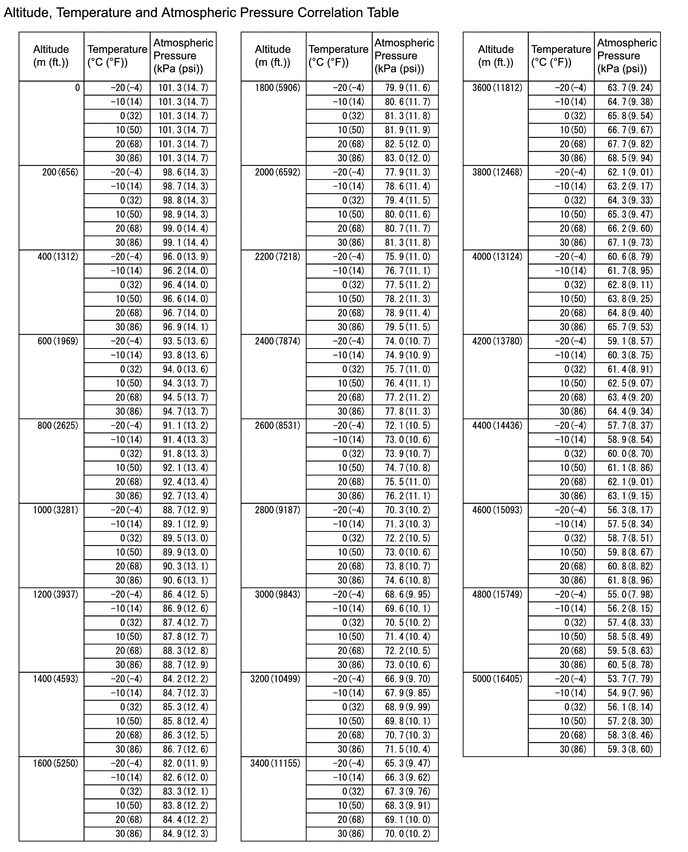
| 4. | READ VALUE USING GTS (ATMOSPHERIC PRESSURE) |
(a) Enter the following menus.
Powertrain > Engine > Data List| Tester Display |
|---|
| Atmospheric Pressure |
(b) Using the table, read the normal atmospheric pressure value for the applicable altitude and temperature.
HINT:
- Standard atmospheric pressure is approximately 101 kPa(abs) (15 psi(abs)).
- For every 100 m (328 ft.) increase in altitude, atmospheric pressure drops by approximately 1 kPa (0.15 psi). This varies by weather.
(c) Compare the Atmospheric pressure value in the Data List with the normal atmospheric value from the table.
| Result | Proceed to |
|---|---|
| Other than the following | A |
| Difference between Atmospheric Pressure in the Data List and normal atmospheric pressure value is 10 kPa (1.45 psi) or more. | B |
| B |
 | REPLACE ECM |
|

| 5. | READ VALUE USING GTS (INTAKE AIR TEMPERATURE) |
(a) Enter the following menus.
Powertrain > Engine > Data List| Tester Display |
|---|
| Intake Air Temperature |
(b) Read the Data List after cooling the engine sufficiently.
| Result | Proceed to |
|---|---|
| Other than the following | A |
| Difference between Intake Air Temperature in the Data List and actual outside air temperature value is 15°C (27°F) or more. | B |
| B |
 | GO TO STEP 17 |
|

| 6. | INSPECT MASS AIR FLOW METER SUB-ASSEMBLY |
(a) Inspect the mass air flow meter sub-assembly, referring to On-vehicle Inspection for Mass Air Flow Meter.
Click here

(b) Inspect the mass air flow meter sub-assembly, referring to Inspection for Mass Air Flow Meter.
Click here

HINT:
Perform "Inspection After Repair" after replacing the mass air flow meter sub-assembly.
Click here

| NG |
 | GO TO STEP 15 |
|

| 7. | INSPECT NO. 2 TURBO PRESSURE SENSOR |
Click here

| NG |
 | GO TO STEP 13 |
|

| 8. | INSPECT E.F.I. VACUUM SENSOR ASSEMBLY |
Click here

| NG |
 | GO TO STEP 11 |
|

| 9. | CLEAR DTC |
(a) Clear the DTCs.
Powertrain > Engine > Clear DTCs(b) Turn the ignition switch off and wait for at least 30 seconds.
|

| 10. | CHECK WHETHER DTC OUTPUT RECURS (DTC P023400) |
(a) Drive the vehicle in accordance with the driving pattern described in Confirmation Driving Pattern.
(b) Enter the following menus.
Powertrain > Engine > Utility| Tester Display |
|---|
| All Readiness |
(c) Input the DTC: P023400.
(d) Check the DTC judgment result.
| Result | Proceed to |
|---|---|
| NORMAL (DTCs are not output) | A |
| ABNORMAL (P023400 is output) | B |
| A |
 | END |
| B |
 | REPLACE ECM |
| 11. | CHECK HARNESS AND CONNECTOR |
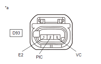
(a) Disconnect the E.F.I. vacuum sensor assembly connector.
(b) Turn the ignition switch to ON.
| (c) Measure the voltage according to the value(s) in the table below. Standard Voltage:
|
|
(d) Turn the ignition switch off and wait for at least 30 seconds.
(e) Measure the resistance according to the value(s) in the table below.
Standard Resistance:
| Tester Connection | Condition | Specified Condition |
|---|---|---|
| D93-3(VC) - D93-2(PIC) | Ignition switch off | 171 to 189 kΩ |
| D93-1(E2) - Body ground | Always | Below 1 Ω |
| OK |
 | REPLACE E.F.I. VACUUM SENSOR ASSEMBLY |
|

| 12. | CHECK HARNESS AND CONNECTOR (E.FI. VACUUM SENSOR ASSEMBLY - ECM) |
(a) Disconnect the E.F.I. vacuum sensor assembly connector.
(b) Disconnect the ECM connector.
(c) Measure the resistance according to the value(s) in the table below.
Standard Resistance:
| Tester Connection | Condition | Specified Condition |
|---|---|---|
| D93-3(VC) - D104-82(VCPR) | Always | Below 1 Ω |
| D93-2(PIC) - D104-105(PIC) | Always | Below 1 Ω |
| D93-1(E2) - D104-81(EPIC) | Always | Below 1 Ω |
| D93-3(VC) or D104-82(VCPR) - Body ground and other terminals | Always | 10 kΩ or higher |
| D93-2(PIC) or D104-105(PIC) - Body ground and other terminals | Always | 10 kΩ or higher |
| OK |
 | REPLACE ECM |
| NG |
 | REPAIR OR REPLACE HARNESS OR CONNECTOR |
| 13. | CHECK HARNESS AND CONNECTOR |
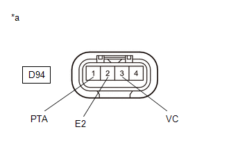
(a) Disconnect the No. 2 turbo pressure sensor connector.
(b) Turn the ignition switch to ON.
| (c) Measure the voltage according to the value(s) in the table below. Standard Voltage:
|
|
(d) Turn the ignition switch off and wait for at least 30 seconds.
(e) Measure the resistance according to the value(s) in the table below.
Standard Resistance:
| Tester Connection | Condition | Specified Condition |
|---|---|---|
| D94-3(VC) - D94-1(PTA) | Ignition switch off | 171 to 189 kΩ |
| D94-2(E2) - Body ground | Always | Below 1 Ω |
| OK |
 | REPLACE NO. 2 TURBO PRESSURE SENSOR |
|

| 14. | CHECK HARNESS AND CONNECTOR (NO. 2 TURBO PRESSURE SENSOR - ECM) |
(a) Disconnect the No. 2 turbo pressure sensor connector.
(b) Disconnect the ECM connector.
(c) Measure the resistance according to the value(s) in the table below.
Standard Resistance:
| Tester Connection | Condition | Specified Condition |
|---|---|---|
| D94-3(VC) - D104-80(VPTA) | Always | Below 1 Ω |
| D94-1(PTA) - D104-103(PTA) | Always | Below 1 Ω |
| D94-2(E2) - D104-79(EPTA) | Always | Below 1 Ω |
| D94-3(VC) or D104-80(VPTA) - Body ground and other terminals | Always | 10 kΩ or higher |
| D94-1(PTA) or D104-103(PTA) - Body ground and other terminals | Always | 10 kΩ or higher |
| OK |
 | REPLACE ECM |
| NG |
 | REPAIR OR REPLACE HARNESS OR CONNECTOR |
| 15. | CHECK HARNESS AND CONNECTOR |
(a) Disconnect the mass air flow meter sub-assembly connector.
(b) Turn the ignition switch to ON.
| (c) Measure the voltage according to the value(s) in the table below. Standard Voltage:
|
|
(d) Turn the ignition switch off and wait for at least 30 seconds.
(e) Measure the resistance according to the value(s) in the table below.
Standard Resistance:
| Tester Connection | Condition | Specified Condition |
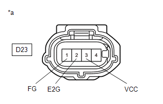
|---|---|---|
| D23-3(VCC) - D23-1(FG) | Ignition switch off | 2.09 to 2.31 kΩ |
| D23-2(E2G) - Body ground | Always | Below 1 Ω |
HINT:
Perform "Inspection After Repair" after replacing the mass air flow meter sub-assembly.
Click here

| OK |
 | REPLACE MASS AIR FLOW METER SUB-ASSEMBLY |
|

| 16. | CHECK HARNESS AND CONNECTOR (MASS AIR FLOW METER SUB-ASSEMBLY - ECM) |
(a) Disconnect the mass air flow meter sub-assembly connector.
(b) Disconnect the ECM connector.
(c) Measure the resistance according to the value(s) in the table below.
Standard Resistance:
| Tester Connection | Condition | Specified Condition |
|---|---|---|
| D23-3(VCC) - D104-84(VCVG) | Always | Below 1 Ω |
| D23-1(FG) - D104-107(VG) | Always | Below 1 Ω |
| D23-2(E2G) - D104-83(E2G) | Always | Below 1 Ω |
| D23-3(VCC) or D104-84(VCVG) - Body ground and other terminals | Always | 10 kΩ or higher |
| D23-1(FG) or D104-107(VG) - Body ground and other terminals | Always | 10 kΩ or higher |
| OK |
 | REPLACE ECM |
| NG |
 | REPAIR OR REPLACE HARNESS OR CONNECTOR |
| 17. | INSPECT MASS AIR FLOW METER SUB-ASSEMBLY (INTAKE AIR TEMPERATURE SENSOR) |
Click here

HINT:
Perform "Inspection After Repair" after replacing the mass air flow meter sub-assembly.
Click here

| NG |
 | REPLACE MASS AIR FLOW METER SUB-ASSEMBLY |
|

| 18. | CHECK HARNESS AND CONNECTOR (MASS AIR FLOW METER SUB-ASSEMBLY - ECM) |
(a) Disconnect the mass air flow meter sub-assembly connector.
(b) Disconnect the ECM connector.
(c) Measure the resistance according to the value(s) in the table below.
Standard Resistance:
| Tester Connection | Condition | Specified Condition |
|---|---|---|
| D23-4(THA) - D104-106(THA) | Always | Below 1 Ω |
| D23-2(E2G) - D104-83(E2G) | Always | Below 1 Ω |
| D23-4(THA) or D104-106(THA) - Body ground and other terminals | Always | 10 kΩ or higher |
| OK |
 | REPLACE ECM |
| NG |
 | REPAIR OR REPLACE HARNESS OR CONNECTOR |
 Throttle/Pedal Position Sensor/Switch "B" Circuit Short to Ground (P022011)
DESCRIPTION Refer to DTC P012011. Click here
DTC No. Detection Item DTC Detection Condition Trouble Area MIL Note P022011 Throttle/Pedal Position Sensor/Switch "B" Circuit Short to Ground The output voltage of VTA2 is below 2...
 Turbocharger/Supercharger Boost Sensor "A" Circuit Short to Ground (P023511)
DESCRIPTION The internal sensor in the No. 2 turbo pressure sensor detects the air outlet duct internal pressure as a voltage.
DTC No. Detection Item DTC Detection Condition Trouble Area MIL Note P023511 Turbocharger/Supercharger Boost Sensor "A" Circuit Short to Ground The output voltage from the No...
Other information:
Toyota Yaris XP210 (2020-2026) Reapir and Service Manual: Removal
REMOVAL PROCEDURE 1. RECOVER REFRIGERANT FROM REFRIGERATION SYSTEM Click here 2. REMOVE HEADLIGHT ASSEMBLY LH Click here 3. REMOVE HEADLIGHT ASSEMBLY RH HINT: Use the same procedure as for the LH side. 4. REMOVE NO. 1 AIR CLEANER INLET Click here 5...
Toyota Yaris XP210 (2020-2026) Reapir and Service Manual: Knock Sensor 1 Bank 1 or Single Sensor Circuit Short to Battery or Open (P032515)
DESCRIPTION Refer to DTC P032511. Click here HINT: When DTC P032515 is stored, the ECM enters fail-safe mode. During fail-safe mode, the ignition timing is delayed to its maximum retardation. Fail-safe mode continues until the ignition switch is turned off...
Categories
- Manuals Home
- Toyota Yaris Owners Manual
- Toyota Yaris Service Manual
- Immobilizer System
- Power Integration No.1 System Missing Message (B235287,B235587,B235787-B235987)
- Fuse Panel Description
- New on site
- Most important about car
Turning the Engine Off
Stop the vehicle completely. Manual transaxle: Shift into neutral and set the parking brake.Automatic transaxle: Shift the selector lever to the P position and set the parking brake.
Press the push button start to turn off the engine. The ignition position is off.