Toyota Yaris: Sfi System / Throttle/Pedal Position Sensor/Switch "B" Circuit Short to Ground (P022011)
DESCRIPTION
Refer to DTC P012011.
Click here

| DTC No. | Detection Item | DTC Detection Condition | Trouble Area | MIL | Note |
|---|---|---|---|---|---|
| P022011 | Throttle/Pedal Position Sensor/Switch "B" Circuit Short to Ground | The output voltage of VTA2 is below 2.05 V for 2 seconds or more (1 trip detection logic). |
| Comes on | SAE: P0222 |
MONITOR DESCRIPTION
The ECM uses the throttle position sensor to monitor the throttle valve opening angle. If the VTA2 terminal voltage is less than the threshold, the ECM will illuminate the MIL and store this DTC.
MONITOR STRATEGY
| Frequency of Operation | Continuous |
CONFIRMATION DRIVING PATTERN
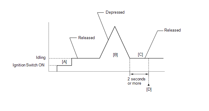
- Connect the GTS to the DLC3.
- Turn the ignition switch to ON.
- Turn the GTS on.
- Clear the DTCs (even if no DTCs are stored, perform the clear DTC procedure).
- Turn the ignition switch off and wait for at least 30 seconds.
- Turn the ignition switch to ON [A].
- Turn the GTS on.
- Start the engine.
- With the vehicle stationary, fully depress and release the accelerator pedal [B].
- Idle the engine for 2 seconds or more [C].
- Enter the following menus: Powertrain / Engine / Trouble Codes [D].
-
Read the pending DTCs.
HINT:
- If a pending DTC is output, the system is malfunctioning.
- If a pending DTC is not output, perform the following procedure.
- Enter the following menus: Powertrain / Engine / Utility / All Readiness.
- Input the DTC: P022011.
-
Check the DTC judgment result.
GTS Display
Description
NORMAL
- DTC judgment completed
- System normal
ABNORMAL
- DTC judgment completed
- System abnormal
INCOMPLETE
- DTC judgment not completed
- Perform driving pattern after confirming DTC enabling conditions
HINT:
- If the judgment result is NORMAL, the system is normal.
- If the judgment result is ABNORMAL, the system is malfunctioning.
- If the judgment result is INCOMPLETE, perform steps [B] through [D] again.
FAIL-SAFE
When this DTC is stored, the ECM enters fail-safe mode. During fail-safe mode, the ECM cuts the current to the throttle actuator, and the throttle valve is returned to a 7.5° throttle valve opening angle by the return spring. The ECM then adjusts the engine output by controlling the fuel injection (intermittent fuel-cut) and ignition timing, in accordance with the accelerator pedal angle, to allow the vehicle to continue running at a minimal speed. If the accelerator pedal is depressed firmly and gently, the vehicle can be driven slowly.
Fail-safe mode continues until a pass condition is detected, and the ignition switch is turned off.
WIRING DIAGRAM
Refer to DTC P012011.
Click here

CAUTION / NOTICE / HINT
HINT:
Read Freeze Frame Data using the GTS. The ECM records vehicle and driving condition information as Freeze Frame Data the moment a DTC is stored. When troubleshooting, Freeze Frame Data can help determine if the vehicle was moving or stationary, if the engine was warmed up or not, if the air fuel ratio was lean or rich, and other data from the time the malfunction occurred.
PROCEDURE
| 1. | READ VALUE USING GTS (THROTTLE POSITION SENSOR NO.2 VOLTAGE) |
(a) Read the values displayed on the GTS.
Powertrain > Engine > Data List| Tester Display |
|---|
| Throttle Position Sensor No.2 Voltage |
(b) Disconnect the throttle body with motor assembly connector.
(c) Compare the value of the Data List item Throttle Position Sensor No.2 Voltage after disconnecting the throttle body with motor assembly connector to the value when the connector was connected.
| Result | Proceed to |
|---|---|
| Changes from below 2.05 V to higher than 4.75 V | A |
| Does not change from below 2.05 V | B |
| A |
 | REPLACE THROTTLE BODY WITH MOTOR ASSEMBLY |
|

| 2. | CHECK HARNESS AND CONNECTOR (THROTTLE POSITION SENSOR - ECM) |
(a) Disconnect the throttle body with motor assembly connector.
(b) Disconnect the ECM connector.
(c) Measure the resistance according to the value(s) in the table below.
Standard Resistance:
| Tester Connection | Condition | Specified Condition |
|---|---|---|
| D19-5(VC) - D104-109(VCTA) | Always | Below 1 Ω |
| D19-4(VTA2) or D104-87(VTA2) - Body ground | Always | 10 kΩ or higher |
| OK |
 | REPLACE ECM |
| NG |
 | REPAIR OR REPLACE HARNESS OR CONNECTOR |
 Cylinder 1 Injector "A" Circuit Open (P020113-P020313,P062D13)
DESCRIPTION The D-4S system has two fuel injection systems. One is an in-cylinder direct injection system that directly injects pressurized fuel into the combustion chamber...
 Turbocharger/Supercharger "A" Overboost Condition (P023400)
DESCRIPTION Refer to DTC P003312. Click here
DTC No. Detection Item DTC Detection Condition Trouble Area MIL Note P023400 Turbocharger/Supercharger "A" Overboost Condition Boost pressure exceeds the threshold value (calculated from turbocharger speed upper limit value)...
Other information:
Toyota Yaris XP210 (2020-2025) Reapir and Service Manual: Removal
REMOVAL PROCEDURE 1. REMOVE RAIN SENSOR COVER (a) Disengage the claws and guide to remove the rain sensor cover. 2. REMOVE RAIN SENSOR (a) Release the stopper by pulling it out as shown in the illustration. *a Stopper Release Separate in this Direction (b) Separate the rain sensor from the windshield glass as shown in the illustration...
Toyota Yaris XP210 (2020-2025) Reapir and Service Manual: Rear Door Left Speaker Circuit Actuator Stuck (B1AB071)
DESCRIPTION This DTC is output when a malfunction occurs in the left side rear speaker system. DTC No. Detection Item DTC Detection Condition Trouble Area B1AB071 Rear Door Left Speaker Circuit Actuator Stuck When starting the system from IG OFF → ACC ON, the stereo component equalizer assembly detects a malfunction in the left side rear speaker system* Harness or connector Rear speaker assembly LH Stereo component equalizer assembly HINT: *: To prevent false positives, fault monitoring is not performed in the following conditions: Auxiliary battery voltage has decreased to 9...
Categories
- Manuals Home
- Toyota Yaris Owners Manual
- Toyota Yaris Service Manual
- Fuse Panel Description
- G16e-gts (engine Mechanical)
- Removal
- New on site
- Most important about car
Supplemental Restraint System (SRS) Precautions
The front and side supplemental restraint systems (SRS) include different types of air bags. Please verify the different types of air bags which are equipped on your vehicle by locating the “SRS AIRBAG” location indicators. These indicators are visible in the area where the air bags are installed.
The air bags are installed in the following locations:
The steering wheel hub (driver air bag) The front passenger dashboard (front passenger air bag) The outboard sides of the front seatbacks (side air bags) The front and rear window pillars, and the roof edge along both sides (curtain air bags)