Toyota Yaris: Radio Antenna Cord / Removal
REMOVAL
CAUTION / NOTICE / HINT
HINT:
When the cable is disconnected / reconnected to the auxiliary battery terminal, systems temporarily stop operating. However, each system has a function that completes learning the first time the system is used.
-
Learning completes when vehicle is driven
Effect/Inoperative Function When Necessary Procedures are not Performed
Necessary Procedures
Link
Lane tracing assist system
Drive the vehicle straight ahead at 35 km/h (22 mph) or more for 5 second or more.

Pre-collision system
Stop and start system
Drive the vehicle until stop and start control is permitted (approximately 5 to 60 minutes)

-
Learning completes when vehicle is operated normally
Effect/Inoperative Function When Necessary Procedures are not Performed
Necessary Procedures
Link
Power door lock control system
- Back door opener
Perform door unlock operation with door control switch or electrical key transmitter sub-assembly switch.

Air conditioning system
After the ignition switch is turned to ON, the servo motor standard position is recognized.
-
PROCEDURE
1. REMOVE INSTRUMENT PANEL SUB-ASSEMBLY
Click here

2. REMOVE NO. 1 SIDE DEFROSTER NOZZLE DUCT
Click here

3. REMOVE NO. 2 SIDE DEFROSTER NOZZLE DUCT
Click here

4. REMOVE ANTENNA CORD SUB-ASSEMBLY
(a) Disengage the clamps and guide to remove the antenna cord sub-assembly.
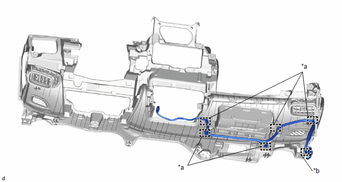
| *a | Clamp | *b | Guide |
5. REMOVE ROOF HEADLINING ASSEMBLY
Click here

6. REMOVE NO. 2 ANTENNA CORD SUB-ASSEMBLY
(a) Remove the 13 adhesive tapes from the roof headlining.
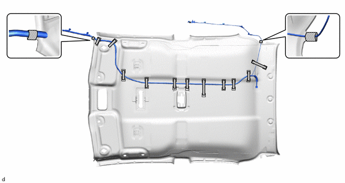
 | Adhesive Tape | - | - |
(b) Remove the No. 2 antenna cord sub-assembly by peeling the No. 2 antenna cord sub-assembly away from the butyl tape.
7. REMOVE NO. 8 ANTENNA CORD SUB-ASSEMBLY
| (a) Disconnect the connector. |
|
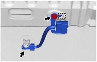
(b) Remove the bolt.
(c) Disengage the guide to remove the No. 8 antenna cord sub-assembly.
 Components
COMPONENTS ILLUSTRATION
*1 NO. 1 SIDE DEFROSTER NOZZLE DUCT *2 NO. 2 SIDE DEFROSTER NOZZLE DUCT *3 ANTENNA CORD SUB-ASSEMBLY - - ILLUSTRATION
*1 NO...
 Installation
INSTALLATION PROCEDURE 1. INSTALL NO. 8 ANTENNA CORD SUB-ASSEMBLY (a) Engage the guide to install the No. 8 antenna cord sub-assembly.
(b) Install the bolt...
Other information:
Toyota Yaris XP210 (2020-2026) Reapir and Service Manual: On-vehicle Inspection
ON-VEHICLE INSPECTION PROCEDURE 1. INSPECT CANISTER (FUEL SUCTION PLATE SUB-ASSEMBLY) (for Fuel Tank Cap Method) (a) Inspect evaporative emission control system. Click here (b) Check for clogs in the air filter (when not using the GTS). (1) Start the engine...
Toyota Yaris XP210 (2020-2026) Reapir and Service Manual: On-vehicle Inspection
ON-VEHICLE INSPECTION PROCEDURE 1. INSPECT COOLING FAN SYSTEM CAUTION: To prevent injury due to contact with an operating cooling fan, keep your hands and clothing away from the cooling fan when inspecting the cooling fan system. (a) Connect the GTS to the DLC3...
Categories
- Manuals Home
- Toyota Yaris Owners Manual
- Toyota Yaris Service Manual
- Fuel Gauge
- Power Integration No.1 System Missing Message (B235287,B235587,B235787-B235987)
- Fuse Panel Description
- New on site
- Most important about car
Front Seat Belt Pretensioners
The front seat belt pretensioners are designed to deploy in moderate or severe frontal, near frontal collisions.
In addition, the pretensioners operate when a side collision or a rollover accident is detected. The pretensioners operate differently depending on what types of air bags are equipped. For more details about the seat belt pretensioner operation, refer to the SRS Air Bag Deployment Criteria.