Toyota Yaris: Lighting System / Instrument Panel Illumination does not Turn On
DESCRIPTION
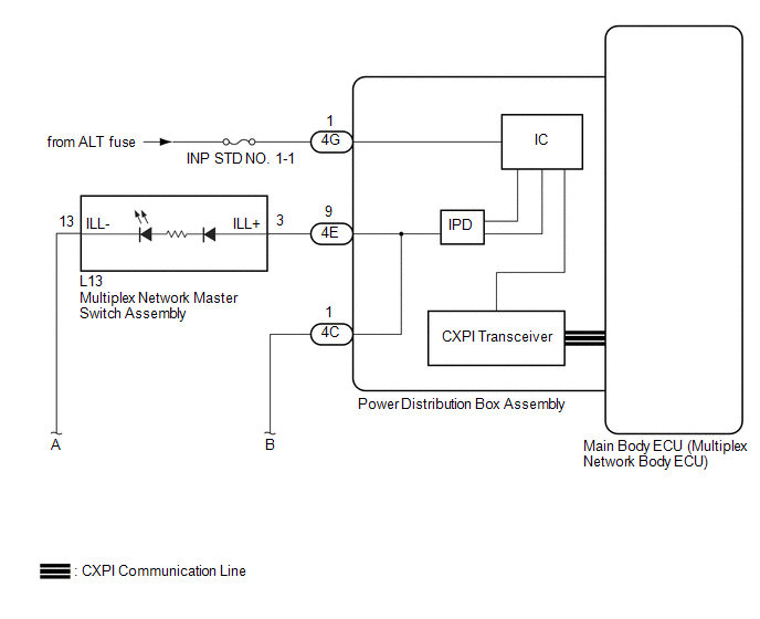
The power distribution box assembly controls the instrument panel illuminations.
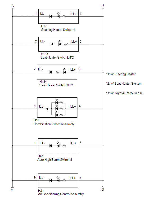
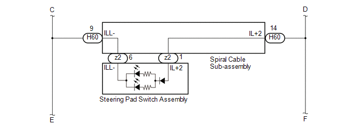
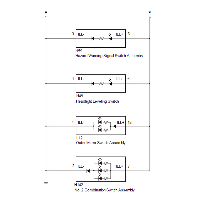
WIRING DIAGRAM
CAUTION / NOTICE / HINT
NOTICE:
- Inspect the fuses for circuits related to this system before performing the following procedure.
-
Before replacing the main body ECU (multiplex network body ECU), refer to Registration.
Click here

PROCEDURE
| 1. | READ VALUE USING GTS |
(a) Turn the light control switch to the TAIL position.
(b) Read the Data List according to the display on the GTS.
Body Electrical > Power Distribution Box > Data List| Tester Display | Measurement Item | Range | Normal Condition | Diagnostic Note |
|---|---|---|---|---|
| Panel Light Fuse Shut Off Status | Panel Light Fuse condition | OFF or ON | OFF: Fuse not shut off ON: Fuse shut off | - |
| Tester Display |
|---|
| Panel Light Fuse Shut Off Status |
OK:
The Data List value displays "OFF".
| NG |
 | GO TO STEP 3 |
|

| 2. | READ VALUE USING GTS |
(a) Read the Data List according to the display on the GTS.
Body Electrical > Power Distribution Box > Data List| Tester Display | Measurement Item | Range | Normal Condition | Diagnostic Note |
|---|---|---|---|---|
| Panel Light Input Signal | Panel light input condition | OFF or ON | OFF: Light control switch not in tail position ON: Light control switch in tail position | - |
| Tester Display |
|---|
| Panel Light Input Signal |
OK:
The GTS display changes.
| OK |
 | REPLACE POWER DISTRIBUTION BOX ASSEMBLY |
| NG |
 | REPLACE MAIN BODY ECU (MULTIPLEX NETWORK BODY ECU) |
| 3. | INSPECT OUTER MIRROR SWITCH ASSEMBLY |
(a) Disconnect the L12 outer mirror switch assembly connector.
(b) Turn the light control switch to the TAIL position.
(c) Read the Data List according to the display on the GTS.
Body Electrical > Power Distribution Box > Data List| Tester Display | Measurement Item | Range | Normal Condition | Diagnostic Note |
|---|---|---|---|---|
| Panel Light Fuse Shut Off Status | Panel Light Fuse condition | OFF or ON | OFF: Fuse not shut off ON: Fuse shut off | - |
| Tester Display |
|---|
| Panel Light Fuse Shut Off Status |
OK:
The Data List value displays "OFF".
| OK |
 | REPLACE OUTER MIRROR SWITCH ASSEMBLY |
|

| 4. | INSPECT MULTIPLEX NETWORK MASTER SWITCH ASSEMBLY |
(a) Disconnect the L13 multiplex network master switch assembly connector.
(b) Connect the GTS to the DLC3.
(c) Turn the light control switch to the TAIL position.
(d) Read the Data List according to the display on the GTS.
Body Electrical > Power Distribution Box > Data List| Tester Display | Measurement Item | Range | Normal Condition | Diagnostic Note |
|---|---|---|---|---|
| Panel Light Fuse Shut Off Status | Panel Light Fuse condition | OFF or ON | OFF: Fuse not shut off ON: Fuse shut off | - |
| Tester Display |
|---|
| Panel Light Fuse Shut Off Status |
OK:
The Data List value displays "OFF".
| Result | Proceed to |
|---|---|
| OK | A |
| NG (w/ Toyota Safety Sense) | B |
| NG (w/o Toyota Safety Sense) | C |
| A |
 | REPLACE MULTIPLEX NETWORK MASTER SWITCH ASSEMBLY |
| C |
 | GO TO STEP 6 |
|

| 5. | INSPECT AUTO HIGH BEAM SWITCH |
(a) Disconnect the H47 auto high beam switch connector.
(b) Turn the light control switch to the TAIL position.
(c) Read the Data List according to the display on the GTS.
Body Electrical > Power Distribution Box > Data List| Tester Display | Measurement Item | Range | Normal Condition | Diagnostic Note |
|---|---|---|---|---|
| Panel Light Fuse Shut Off Status | Panel Light Fuse condition | OFF or ON | OFF: Fuse not shut off ON: Fuse shut off | - |
| Tester Display |
|---|
| Panel Light Fuse Shut Off Status |
OK:
The Data List value displays "OFF".
| OK |
 | REPLACE AUTO HIGH BEAM SWITCH |
| NG |
 | GO TO STEP 6 |
| 6. | INSPECT HEADLIGHT LEVELING SWITCH |
(a) Disconnect the H49 headlight leveling switch connector.
(b) Turn the light control switch to the TAIL position.
(c) Read the Data List according to the display on the GTS.
Body Electrical > Power Distribution Box > Data List| Tester Display | Measurement Item | Range | Normal Condition | Diagnostic Note |
|---|---|---|---|---|
| Panel Light Fuse Shut Off Status | Panel Light Fuse condition | OFF or ON | OFF: Fuse not shut off ON: Fuse shut off | - |
| Tester Display |
|---|
| Panel Light Fuse Shut Off Status |
OK:
The Data List value displays "OFF".
| Result | Proceed to |
|---|---|
| OK | A |
| NG (w/ Steering Heater) | B |
| NG (w/o Steering Heater) | C |
| A |
 | REPLACE HEADLIGHT LEVELING SWITCH |
| C |
 | GO TO STEP 8 |
|

| 7. | INSPECT STEERING HEATER SWITCH |
(a) Disconnect the H57 steering heater switch connector.
(b) Turn the light control switch to the TAIL position.
(c) Read the Data List according to the display on the GTS.
Body Electrical > Power Distribution Box > Data List| Tester Display | Measurement Item | Range | Normal Condition | Diagnostic Note |
|---|---|---|---|---|
| Panel Light Fuse Shut Off Status | Panel Light Fuse condition | OFF or ON | OFF: Fuse not shut off ON: Fuse shut off | - |
| Tester Display |
|---|
| Panel Light Fuse Shut Off Status |
OK:
The Data List value displays "OFF".
| OK |
 | GO TO STEP 8 |
| NG |
 | REPLACE STEERING HEATER SWITCH |
| 8. | INSPECT COMBINATION SWITCH ASSEMBLY |
(a) Disconnect the H18 combination switch assembly connector.
(b) Turn the light control switch to the TAIL position.
(c) Read the Data List according to the display on the GTS.
Body Electrical > Power Distribution Box > Data List| Tester Display | Measurement Item | Range | Normal Condition | Diagnostic Note |
|---|---|---|---|---|
| Panel Light Fuse Shut Off Status | Panel Light Fuse condition | OFF or ON | OFF: Fuse not shut off ON: Fuse shut off | - |
| Tester Display |
|---|
| Panel Light Fuse Shut Off Status |
OK:
The Data List value displays "OFF".
| OK |
 | REPLACE COMBINATION SWITCH ASSEMBLY |
|

| 9. | CONFIRM MODEL |
(a) Choose the model to be inspected.
| Result | Proceed to |
|---|---|
| w/ Seat Heater System | A |
| w/o Seat Heater System | B |
| B |
 | GO TO STEP 12 |
|

| 10. | INSPECT SEAT HEATER SWITCH LH |
(a) Disconnect the H135 seat heater switch LH connector.
(b) Turn the light control switch to the TAIL position.
(c) Read the Data List according to the display on the GTS.
Body Electrical > Power Distribution Box > Data List| Tester Display | Measurement Item | Range | Normal Condition | Diagnostic Note |
|---|---|---|---|---|
| Panel Light Fuse Shut Off Status | Panel Light Fuse condition | OFF or ON | OFF: Fuse not shut off ON: Fuse shut off | - |
| Tester Display |
|---|
| Panel Light Fuse Shut Off Status |
OK:
The Data List value displays "OFF".
| OK |
 | REPLACE SEAT HEATER SWITCH LH |
|

| 11. | INSPECT SEAT HEATER SWITCH RH |
(a) Disconnect the H134 seat heater switch RH connector.
(b) Turn the light control switch to the TAIL position.
(c) Read the Data List according to the display on the GTS.
Body Electrical > Power Distribution Box > Data List| Tester Display | Measurement Item | Range | Normal Condition | Diagnostic Note |
|---|---|---|---|---|
| Panel Light Fuse Shut Off Status | Panel Light Fuse condition | OFF or ON | OFF: Fuse not shut off ON: Fuse shut off | - |
| Tester Display |
|---|
| Panel Light Fuse Shut Off Status |
OK:
The Data List value displays "OFF".
| OK |
 | GO TO STEP 12 |
| NG |
 | REPLACE SEAT HEATER SWITCH RH |
| 12. | INSPECT AIR CONDITIONING CONTROL ASSEMBLY |
(a) Disconnect the H31 air conditioning control assembly connector.
(b) Turn the light control switch to the TAIL position.
(c) Read the Data List according to the display on the GTS.
Body Electrical > Power Distribution Box > Data List| Tester Display | Measurement Item | Range | Normal Condition | Diagnostic Note |
|---|---|---|---|---|
| Panel Light Fuse Shut Off Status | Panel Light Fuse condition | OFF or ON | OFF: Fuse not shut off ON: Fuse shut off | - |
| Tester Display |
|---|
| Panel Light Fuse Shut Off Status |
OK:
The Data List value displays "OFF".
| OK |
 | REPLACE AIR CONDITIONING CONTROL ASSEMBLY |
|

| 13. | INSPECT STEERING PAD SWITCH ASSEMBLY |
(a) Disconnect the z2 steering pad switch assembly connector.
(b) Turn the light control switch to the TAIL position.
(c) Read the Data List according to the display on the GTS.
Body Electrical > Power Distribution Box > Data List| Tester Display | Measurement Item | Range | Normal Condition | Diagnostic Note |
|---|---|---|---|---|
| Panel Light Fuse Shut Off Status | Panel Light Fuse condition | OFF or ON | OFF: Fuse not shut off ON: Fuse shut off | - |
| Tester Display |
|---|
| Panel Light Fuse Shut Off Status |
OK:
The Data List value displays "OFF".
| OK |
 | REPLACE STEERING PAD SWITCH ASSEMBLY |
|

| 14. | INSPECT SPIRAL CABLE SUB-ASSEMBLY |
(a) Disconnect the H60 spiral cable sub-assembly connector.
(b) Turn the light control switch to the TAIL position.
(c) Read the Data List according to the display on the GTS.
Body Electrical > Power Distribution Box > Data List| Tester Display | Measurement Item | Range | Normal Condition | Diagnostic Note |
|---|---|---|---|---|
| Panel Light Fuse Shut Off Status | Panel Light Fuse condition | OFF or ON | OFF: Fuse not shut off ON: Fuse shut off | - |
| Tester Display |
|---|
| Panel Light Fuse Shut Off Status |
OK:
The Data List value displays "OFF".
| OK |
 | REPLACE SPIRAL CABLE SUB-ASSEMBLY |
|

| 15. | INSPECT NO. 2 COMBINATION SWITCH ASSEMBLY |
(a) Disconnect the H142 No. 2 combination switch assembly connector.
(b) Turn the light control switch to the TAIL position.
(c) Read the Data List according to the display on the GTS.
Body Electrical > Power Distribution Box > Data List| Tester Display | Measurement Item | Range | Normal Condition | Diagnostic Note |
|---|---|---|---|---|
| Panel Light Fuse Shut Off Status | Panel Light Fuse condition | OFF or ON | OFF: Fuse not shut off ON: Fuse shut off | - |
| Tester Display |
|---|
| Panel Light Fuse Shut Off Status |
OK:
The Data List value displays "OFF".
| OK |
 | REPLACE NO. 2 COMBINATION SWITCH ASSEMBLY |
|

| 16. | INSPECT HAZARD WARNING SIGNAL SWITCH ASSEMBLY |
(a) Disconnect the H59 hazard warning signal switch assembly connector.
(b) Turn the light control switch to the TAIL position.
(c) Read the Data List according to the display on the GTS.
Body Electrical > Power Distribution Box > Data List| Tester Display | Measurement Item | Range | Normal Condition | Diagnostic Note |
|---|---|---|---|---|
| Panel Light Fuse Shut Off Status | Panel Light Fuse condition | OFF or ON | OFF: Fuse not shut off ON: Fuse shut off | - |
| Tester Display |
|---|
| Panel Light Fuse Shut Off Status |
OK:
The Data List value displays "OFF".
| OK |
 | REPLACE HAZARD WARNING SIGNAL SWITCH ASSEMBLY |
|

| 17. | CHECK HARNESS AND CONNECTOR (EACH SWITCH - POWER DISTRIBUTION BOX ASSEMBLY) |
(a) Disconnect the L12 outer mirror switch assembly connector.
(b) Disconnect the L13 multiplex network master switch assembly connector.
(c) Disconnect the H47 auto high beam switch connector. (w/ Toyota Safety Sense)
(d) Disconnect the H49 headlight leveling switch connector.
(e) Disconnect the H57 steering heater switch connector. (w/ steering heater)
(f) Disconnect the H18 combination switch assembly connector.
(g) Disconnect the H142 No. 2 combination switch assembly connector.
(h) Disconnect the H135 seat heater switch LH connector. (w/ Seat Heater System)
(i) Disconnect the H134 seat heater switch RH connector. (w/ Seat Heater System)
(j) Disconnect the H31 air conditioning control assembly connector.
(k) Disconnect the z2 steering pad switch assembly connector.
(l) Disconnect the H60 spiral cable sub-assembly connector.
(m) Disconnect the H59 hazard warning signal switch assembly connector.
(n) Disconnect the cable from the negative (-) auxiliary battery terminal.
(o) Disconnect the 4E and 4C power distribution box assembly connectors.
(p) Measure the resistance according to the value(s) in the table below.
Standard Resistance:
| Tester Connection | Condition | Specified Condition |
|---|---|---|
| L12-12 (ILL+) or 4C-1 - Body ground | Always | Below 1 Ω |
| L13-3 (ILL+) or 4E-9 - Body ground | Always | Below 1 Ω |
| H47-6 (ILL+) or 4C-1 - Body ground*1 | Always | Below 1 Ω |
| H49-6 (ILL+) or 4C-1 - Body ground | Always | Below 1 Ω |
| H57-6 (ILL+) or 4C-1 - Body ground*2 | Always | Below 1 Ω |
| H18-4 (ILL+) or 4C-1 - Body ground | Always | Below 1 Ω |
| H142-7 (ILL+) or 4C-1 - Body ground | Always | Below 1 Ω |
| H135-5 (ILL+) or 4C-1 - Body ground*3 | Always | Below 1 Ω |
| H134-5 (ILL+) or 4C-1 - Body ground*3 | Always | Below 1 Ω |
| H31-8 (ILL+) or 4C-1 - Body ground | Always | Below 1 Ω |
| z2-1 (ILL+2) or 4C-1 - Body ground | Always | Below 1 Ω |
| H60-14 (IL+2) or 4C-1 - Body ground | Always | Below 1 Ω |
| H59-6 (ILL+) or 4C-1 - Body ground | Always | Below 1 Ω |
- *1: w/ Toyota Safety Sense
- *2: w/ Steering Heater
- *3: w/ Seat Heater System
| OK |
 | REPLACE POWER DISTRIBUTION BOX ASSEMBLY |
| NG |
 | REPAIR OR REPLACE HARNESS OR CONNECTOR |
 Push Start Switch Illumination Circuit
DESCRIPTION The illuminated entry system controls the push start switch illumination. WIRING DIAGRAM
CAUTION / NOTICE / HINT NOTICE: Before replacing the certification ECU (smart key ECU assembly), refer to Registration...
 Door Unlock Detection Switch Circuit
DESCRIPTION The main body ECU (multiplex network body ECU) detects the condition of each door unlock detection switch. WIRING DIAGRAM
CAUTION / NOTICE / HINT NOTICE: Before replacing the main body ECU (multiplex network body ECU), refer to Registration...
Other information:
Toyota Yaris XP210 (2020-2026) Reapir and Service Manual: Brake Switch "A"/"B" Signal Cross Coupled (P05042B)
DESCRIPTION The stop light switch assembly is a duplex system that transmits two signals: STP and ST1-. These two signals are used by the ECM to monitor whether or not the brake system is working properly. If the signals, which indicate the brake pedal is being depressed and released, are detected simultaneously, the ECM interprets this as a malfunction in the stop light switch assembly and stores this DTC...
Toyota Yaris XP210 (2020-2026) Reapir and Service Manual: Installation
INSTALLATION CAUTION / NOTICE / HINT HINT: Use the same procedure for the RH side and LH side. The following procedure is for the LH side. PROCEDURE 1. INSTALL ROOF DRIP SIDE FINISH MOULDING CLIP NOTICE: When installing a new roof drip side finish moulding clip, remove any double-sided tape remaining where the roof drip side finish moulding clips will be installed on the vehicle body and clean the vehicle body with a non-residue solvent...
Categories
- Manuals Home
- Toyota Yaris Owners Manual
- Toyota Yaris Service Manual
- How to use USB mode
- Engine Start Function When Key Battery is Dead
- Removal
- New on site
- Most important about car
Key Suspend Function
If a key is left in the vehicle, the functions of the key left in the vehicle are temporarily suspended to prevent theft of the vehicle.
To restore the functions, press the unlock button on the functions-suspended key in the vehicle.