Toyota Yaris: Lighting System / Door Unlock Detection Switch Circuit
DESCRIPTION
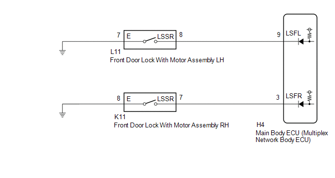
The main body ECU (multiplex network body ECU) detects the condition of each door unlock detection switch.
WIRING DIAGRAM
CAUTION / NOTICE / HINT
NOTICE:
Before replacing the main body ECU (multiplex network body ECU), refer to Registration.
Click here

PROCEDURE
| 1. | READ VALUE USING GTS |
(a) Read the Data List according to the display on the GTS.
Body Electrical > Main Body > Data List| Tester Display | Measurement Item | Range | Normal Condition | Diagnostic Note |
|---|---|---|---|---|
| FR Door Lock Position Switch Status | Front door RH unlock detection switch signal | LOCK or UNLOCK | LOCK: Front door RH locked UNLOCK: Front door RH unlocked | - |
| FL Door Lock Position Switch Status | Front door LH unlock detection switch signal | LOCK or UNLOCK | LOCK: Front door LH locked UNLOCK: Front door LH unlocked | - |
| Tester Display |
|---|
| FR Door Lock Position Switch Status |
| FL Door Lock Position Switch Status |
OK:
Normal conditions listed above are displayed.
| Result | Proceed to |
|---|---|
| OK | A |
| NG ("FR Door Lock Position Switch Status" is not normal) | B |
| NG ("FL Door Lock Position Switch Status" is not normal) | C |
| A |
 | PROCEED TO NEXT SUSPECTED AREA SHOWN IN PROBLEM SYMPTOMS TABLE |
| C |
 | GO TO STEP 4 |
|

| 2. | INSPECT FRONT DOOR LOCK ASSEMBLY LH |
Click here

| NG |
 | REPLACE FRONT DOOR LOCK ASSEMBLY LH |
|

| 3. | CHECK HARNESS AND CONNECTOR (FRONT DOOR LOCK ASSEMBLY LH - MAIN BODY ECU (MULTIPLEX NETWORK BODY ECU) AND BODY GROUND) |
(a) Disconnect the H4 main body ECU (multiplex network body ECU) connector.
(b) Measure the resistance according to the value(s) in the table below.
Standard Resistance:
| Tester Connection | Condition | Specified Condition |
|---|---|---|
| L11-8 (LSSR) - H4-9 (LSFL) | Always | Below 1 Ω |
| L11-8 (LSSR) or H4-9 (LSFL) | Always | 10 kΩ or higher |
| L11-7 (E) - Body ground | Always | Below 1 Ω |
| OK |
 | REPLACE MAIN BODY ECU (MULTIPLEX NETWORK BODY ECU) |
| NG |
 | REPAIR OR REPLACE HARNESS OR CONNECTOR |
| 4. | INSPECT FRONT DOOR LOCK ASSEMBLY RH |
Click here

| NG |
 | REPLACE FRONT DOOR LOCK ASSEMBLY RH |
|

| 5. | CHECK HARNESS AND CONNECTOR (FRONT DOOR LOCK ASSEMBLY RH - MAIN BODY ECU (MULTIPLEX NETWORK BODY ECU) AND BODY GROUND) |
(a) Disconnect the H4 main body ECU (multiplex network body ECU) connector.
(b) Measure the resistance according to the value(s) in the table below.
Standard Resistance:
| Tester Connection | Condition | Specified Condition |
|---|---|---|
| K11-7 (LSSR) - H4-3 (LSFR) | Always | Below 1 Ω |
| K11-7 (LSSR) or H4-3 (LSFR) - Body ground | Always | 10 kΩ or higher |
| K11-8 (E) - Body ground | Always | Below 1 Ω |
| OK |
 | REPLACE MAIN BODY ECU (MULTIPLEX NETWORK BODY ECU) |
| NG |
 | REPAIR OR REPLACE HARNESS OR CONNECTOR |
 Instrument Panel Illumination does not Turn On
DESCRIPTION The power distribution box assembly controls the instrument panel illuminations. WIRING DIAGRAM
CAUTION / NOTICE / HINT NOTICE:
Inspect the fuses for circuits related to this system before performing the following procedure...
 Personal Light
ComponentsCOMPONENTS ILLUSTRATION
*1 MAP LIGHT ASSEMBLY - - RemovalREMOVAL PROCEDURE 1. REMOVE MAP LIGHT ASSEMBLY (a) Using a moulding remover D, disengage the clips to remove the map light assembly as shown in the illustration...
Other information:
Toyota Yaris XP210 (2020-2026) Owner's Manual: Settings
Select the icon on the home screen and display the Settings screen. Switch the tab and select the setting item you want to change. You can customize settings in the setup display as follows: Depending on the grade and specification, the screen display may differ...
Toyota Yaris XP210 (2020-2026) Owner's Manual: Variance Between Actual Road Conditions and Displayed Image
Some variance occurs between the actual road and the displayed road. Such variance in distance perspective could lead to an accident. Note the following conditions that may cause a variance in distance perspective. When the vehicle is tilted due to the weight of passengers and load When the vehicle rear is lowered, the object displayed on the screen appears farther than the actual distance...
Categories
- Manuals Home
- Toyota Yaris Owners Manual
- Toyota Yaris Service Manual
- Fuse Panel Description
- Headlights
- Power Integration No.1 System Missing Message (B235287,B235587,B235787-B235987)
- New on site
- Most important about car
Fuel-Filler Lid and Cap
WARNING
When removing the fuel-filler cap, loosen the cap slightly and wait for any hissing to stop, then remove it
Fuel spray is dangerous. Fuel can burn skin and eyes and cause illness if ingested. Fuel spray is released when there is pressure in the fuel tank and the fuel-filler cap is removed too quickly.