Toyota Yaris: Lighting (int) / Personal Light
Components
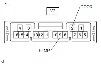
COMPONENTS
ILLUSTRATION
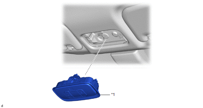
| *1 | MAP LIGHT ASSEMBLY | - | - |
Removal
REMOVAL
PROCEDURE
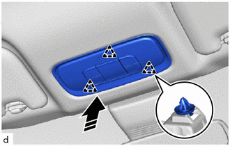
1. REMOVE MAP LIGHT ASSEMBLY
(a) Using a moulding remover D, disengage the clips to remove the map light assembly as shown in the illustration.
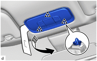
 | Remove in this Direction |
| (b) Disconnect the connector. |
|
Inspection
INSPECTION
PROCEDURE
1. INSPECT MAP LIGHT ASSEMBLY
(a) Check the map light.
| (1) Apply auxiliary battery voltage to the map light assembly and check that the map light comes on. OK:
If the result is not as specified, replace the map light assembly. |
|
(b) Check the door switch.
| (1) Measure the resistance according to the value(s) in the table below. Standard Resistance:
If the result is not as specified, replace the map light assembly. |
|
Installation
INSTALLATION
PROCEDURE
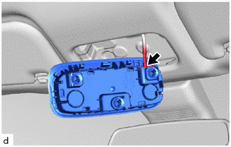
1. INSTALL MAP LIGHT ASSEMBLY
(a) Connect the connector.
(b) Engage the clips to install the map light assembly as shown in the illustration.
 | Install in this Direction |
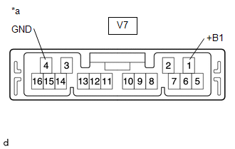
 Door Unlock Detection Switch Circuit
DESCRIPTION The main body ECU (multiplex network body ECU) detects the condition of each door unlock detection switch. WIRING DIAGRAM
CAUTION / NOTICE / HINT NOTICE: Before replacing the main body ECU (multiplex network body ECU), refer to Registration...
 Room Light
ComponentsCOMPONENTS ILLUSTRATION
*1 NO. 1 ROOM LIGHT ASSEMBLY *2 NO. 1 ROOM LIGHT BULB *3 NO. 1 ROOM LIGHT LENS *4 NO. 1 ROOM LIGHT HOUSING RemovalREMOVAL PROCEDURE 1...
Other information:
Toyota Yaris XP210 (2020-2026) Reapir and Service Manual: Problem Symptoms Table
PROBLEM SYMPTOMS TABLE NOTICE: If the main body ECU (multiplex network body ECU) is replaced, refer to the Registration. Click here HINT: Use the table below to help determine the cause of problem symptoms. If multiple suspected areas are listed, the potential causes of the symptoms are listed in order of probability in the "Suspected Area" column of the table...
Toyota Yaris XP210 (2020-2026) Reapir and Service Manual: Vehicle Control History
VEHICLE CONTROL HISTORY NOTICE: Make sure to record any output Vehicle Control History codes before clearing them and checking the Vehicle Control History again. CHECK VEHICLE CONTROL HISTORY (DYNAMIC RADAR CRUISE CONTROL SYSTEM) (a) Read the Vehicle Control History (RoB) according to the display on the GTS...
Categories
- Manuals Home
- Toyota Yaris Owners Manual
- Toyota Yaris Service Manual
- Opening and Closing the Liftgate/Trunk Lid
- To Set Speed
- Diagnostic Trouble Code Chart
- New on site
- Most important about car
Fuel Gauge
The fuel gauge shows approximately how much fuel is remaining in the tank when the ignition is switched ON. We recommend keeping the tank over 1/4 full.
