Toyota Yaris: Wireless Door Lock Control System / Parts Location
PARTS LOCATION
ILLUSTRATION
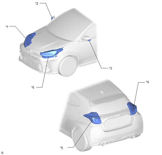
| *1 | HEADLIGHT ASSEMBLY RH - TURN SIGNAL LIGHT | *2 | SIDE TURN SIGNAL LIGHT ASSEMBLY RH |
| *3 | SIDE TURN SIGNAL LIGHT ASSEMBLY LH | *4 | REAR COMBINATION LIGHT ASSEMBLY RH - TURN SIGNAL LIGHT |
| *5 | REAR COMBINATION LIGHT ASSEMBLY LH - TURN SIGNAL LIGHT | *6 | HEADLIGHT ASSEMBLY LH - TURN SIGNAL LIGHT |
ILLUSTRATION
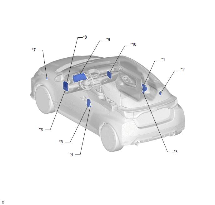
| *1 | FRONT DOOR LOCK WITH MOTOR ASSEMBLY RH | *2 | SMART DOOR CONTROL RECEIVER ASSEMBLY |
| *3 | FRONT DOOR COURTESY LIGHT SWITCH ASSEMBLY RH | *4 | FRONT DOOR COURTESY LIGHT SWITCH ASSEMBLY LH |
| *5 | FRONT DOOR LOCK WITH MOTOR ASSEMBLY LH | *6 | POWER DISTRIBUTION BOX ASSEMBLY - ECU-IGR NO. 2 FUSE - ECU-DCC NO. 2 FUSE - AM2 FUSE - D/L FUSE - DOOR BACK RELAY - ALL DOOR LOCK RELAY - ALL DOOR UNLOCK RELAY |
| *7 | WIRELESS DOOR LOCK BUZZER | *8 | MAIN BODY ECU (MULTIPLEX NETWORK BODY ECU) |
| *9 | COMBINATION METER ASSEMBLY | *10 | CERTIFICATION ECU (SMART KEY ECU ASSEMBLY) |
 Precaution
PRECAUTION PRECAUTIONS WHEN USING GTS (a) When using the GTS with the ignition switch off, connect the GTS to the DLC3 and turn a courtesy light switch on and off at intervals of 1...
 System Diagram
S..
Other information:
Toyota Yaris XP210 (2020-2026) Owner's Manual: How to use Apple CarPlay™
What is Apple CarPlay™? Apple CarPlay™ allows you to make calls, send or receive messages, and listen to music using your iPhone® with the vehicle’s audio system, or search for destinations using the maps. In addition, voice recognition operation is possible using Siri®...
Toyota Yaris XP210 (2020-2026) Reapir and Service Manual: Fail-safe Chart
FAIL-SAFE CHART If any of the following DTCs are stored, the ECM enters fail-safe mode to allow the vehicle to be driven temporarily. DTC No. Fail-safe Operation Fail-safe Deactivation Condition P058A01 P062049 P065C07 P160200 P161A87 P162B87 Generator command is fixed...
Categories
- Manuals Home
- Toyota Yaris Owners Manual
- Toyota Yaris Service Manual
- Power Integration No.1 System Missing Message (B235287,B235587,B235787-B235987)
- Immobilizer System
- Fuse Panel Description
- New on site
- Most important about car
Front Seat Belt Pretensioners
The front seat belt pretensioners are designed to deploy in moderate or severe frontal, near frontal collisions.
In addition, the pretensioners operate when a side collision or a rollover accident is detected. The pretensioners operate differently depending on what types of air bags are equipped. For more details about the seat belt pretensioner operation, refer to the SRS Air Bag Deployment Criteria.