Toyota Yaris: Compressor / Removal
REMOVAL
PROCEDURE
1. RECOVER REFRIGERANT FROM REFRIGERATION SYSTEM
Click here

2. REMOVE NO. 1 ENGINE UNDER COVER ASSEMBLY
Click here

3. REMOVE FAN AND GENERATOR V BELT
Click here

4. DISCONNECT SUCTION HOSE SUB-ASSEMBLY
| (a) Remove the bolt and disconnect the suction hose sub-assembly from the compressor with pulley assembly. |
|
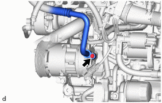
(b) Remove the O-ring from the suction hose sub-assembly.
NOTICE:
Seal the openings of the disconnected parts using vinyl tape to prevent moisture and foreign matter from entering them.
5. DISCONNECT NO. 1 COOLER REFRIGERANT DISCHARGE HOSE
| (a) Remove the bolt and disconnect the No. 1 cooler refrigerant discharge hose from the compressor with pulley assembly. |
|
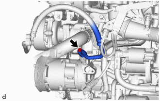
(b) Remove the O-ring from the No. 1 cooler refrigerant discharge hose.
NOTICE:
Seal the openings of the disconnected parts using vinyl tape to prevent moisture and foreign matter from entering them.
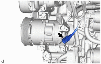
6. REMOVE COMPRESSOR WITH PULLEY ASSEMBLY
| (a) Disconnect the connector. |
|
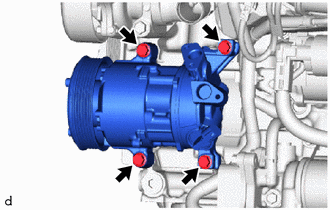
| (b) Remove the 4 bolts and compressor with pulley assembly. |
|
 Components
COMPONENTS ILLUSTRATION
*1 NO. 1 ENGINE UNDER COVER ASSEMBLY *2 SUCTION HOSE SUB-ASSEMBLY *3 NO. 1 COOLER REFRIGERANT DISCHARGE HOSE *4 COMPRESSOR WITH PULLEY ASSEMBLY *5 O-ring - -
Tightening torque for "Major areas involving basic vehicle performance such as moving/turning/stopping" : N*m (kgf*cm, ft...
 Installation
INSTALLATION PROCEDURE 1. INSPECT COMPRESSOR OIL (a) Remove the suction seal cap. (b) Using a screwdriver with its tip wrapped in protective tape, insert the screwdriver through the suction port and set the VST valve (valve inside suction port) to the open position...
Other information:
Toyota Yaris XP210 (2020-2026) Reapir and Service Manual: Installation
INSTALLATION CAUTION / NOTICE / HINT NOTICE: Make sure to use Toyota Genuine Windshield Glass Adhesive (High Modulus Type) or equivalent. HINT: Use the same procedure for the RH side and LH side. The following procedure is for the LH side. PROCEDURE 1...
Toyota Yaris XP210 (2020-2026) Reapir and Service Manual: Steering Pad Switch Circuit
DESCRIPTION The forward recognition camera receives LTA main switch signals from the steering pad switch assembly. WIRING DIAGRAM CAUTION / NOTICE / HINT NOTICE: When replacing the forward recognition camera, always replace it with a new one. If a forward recognition camera which was installed to another vehicle is used, the information stored in the forward recognition camera will not match the information from the vehicle and a DTC may be stored...
Categories
- Manuals Home
- Toyota Yaris Owners Manual
- Toyota Yaris Service Manual
- How to use USB mode
- Headlights
- G16e-gts (engine Mechanical)
- New on site
- Most important about car
Keys

To use the auxiliary key, press the knob and pull out the auxiliary key from the smart key.
