Toyota Yaris: Active Torque Split Awd System / Supply Voltage Circuit Circuit Voltage Out of Range (C123A1C)
DESCRIPTION
When a malfunction has occurred in the power source circuit, the AWD ECU assembly stores DTC C123A1C.
| DTC No. | Detection Item | DTC Detection Condition | Trouble Area | Warning Indicate | Memory |
|---|---|---|---|---|---|
| C123A1C | Supply Voltage Circuit Circuit Voltage Out of Range |
|
| Displayed | Yes |
| Vehicle Condition | |||
|---|---|---|---|
| Pattern 1 | Pattern 2 | ||
| Diagnosis Condition | The vehicle speed is 3 km/h (2 mph) or more | ○ | - |
| Malfunction Status | The IG1 terminal voltage is less than 9.5 V | ○ | - |
| The IG1 terminal voltage is 17 V or more | - | ○ | |
| Detection Time | 10 seconds or more | 3 seconds or more | |
| Number of Trips | 1 trip | 1 trip | |
HINT:
DTC will be output when conditions for either of the patterns in the table above are met.
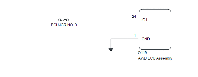
WIRING DIAGRAM
CAUTION / NOTICE / HINT
NOTICE:
- Inspect the fuses for circuits related to this system before performing the following inspection procedure.
-
When the AWD ECU assembly is replaced, before removing the AWD ECU assembly, it is necessary to perform ECU Data Save to save the original AWD ECU assembly information.
Click here

-
After performing repairs, clear the DTCs and check that the DTCs are not output again.
Click here

PROCEDURE
| 1. | CHECK HARNESS AND CONNECTOR (IG1 TERMINAL) |
(a) Turn the ignition switch off.
(b) Disconnect the O119 AWD ECU assembly connector.
(c) Turn the ignition switch to ON.
(d) Measure the voltage according to the value(s) in the table below.
Standard Voltage:
| Tester Connection | Switch Condition | Specified Condition |
|---|---|---|
| O119-24 (IG1) - Body ground | Ignition switch ON | 11 to 14 V |
| NG |
 | REPAIR OR REPLACE HARNESS OR CONNECTOR |
|

| 2. | CHECK HARNESS AND CONNECTOR (GND TERMINAL) |
(a) Turn the ignition switch off.
(b) Disconnect the O119 AWD ECU assembly connector.
(c) Measure the resistance according to the value(s) in the table below.
Standard Resistance:
| Tester Connection | Condition | Specified Condition |
|---|---|---|
| O119-1 (GND) - Body ground | Always | Below 1 Ω |
| OK |
 | REPLACE AWD ECU ASSEMBLY |
| NG |
 | REPAIR OR REPLACE HARNESS OR CONNECTOR |
 Linear Solenoid Power Supply System Circuit Voltage Out of Range (C120C1C)
DESCRIPTION When a malfunction has occurred in the linear solenoid power source system, the AWD ECU assembly stores DTC C120C1C. DTC No. Detection Item DTC Detection Condition Trouble Area Warning Indicate Memory C120C1C Linear Solenoid Power Supply System Circuit Voltage Out of Range When the IG1 terminal voltage is 9...
 Lost Communication with ECM/PCM "A" Missing Message (U010087,U012687,U012987)
DESCRIPTION The AWD ECU assembly receives signals from the ECM, steering sensor and skid control ECU (brake actuator assembly) via CAN communication. DTC No...
Other information:
Toyota Yaris XP210 (2020-2025) Owner's Manual: When Trunk Lid Cannot be Opened
If the vehicle battery is dead or there is a malfunction in the electrical system and the liftgate/trunk lid cannot be opened, perform the following procedure as an emergency measure to open it: WARNING Perform the procedure using a cloth to cover sharp edges which could injure your hands...
Toyota Yaris XP210 (2020-2025) Reapir and Service Manual: Excessive Brake Pedal Travel (No Fluid Leaks and No Air in System)
CAUTION / NOTICE / HINT NOTICE: After replacing the skid control ECU (brake actuator assembly), perform "Calibration". Click here PROCEDURE 1. PRE-INSPECTION (a) Brake pedal inspection (1) Perform a visual inspection and operate the brake pedal to check for any malfunctions...
Categories
- Manuals Home
- Toyota Yaris Owners Manual
- Toyota Yaris Service Manual
- Opening and Closing the Liftgate/Trunk Lid
- Adjustment
- Immobilizer System
- New on site
- Most important about car
Supplemental Restraint System (SRS) Precautions
The front and side supplemental restraint systems (SRS) include different types of air bags. Please verify the different types of air bags which are equipped on your vehicle by locating the “SRS AIRBAG” location indicators. These indicators are visible in the area where the air bags are installed.
The air bags are installed in the following locations:
The steering wheel hub (driver air bag) The front passenger dashboard (front passenger air bag) The outboard sides of the front seatbacks (side air bags) The front and rear window pillars, and the roof edge along both sides (curtain air bags)