Toyota Yaris: Wireless Door Lock Control System / System Diagram
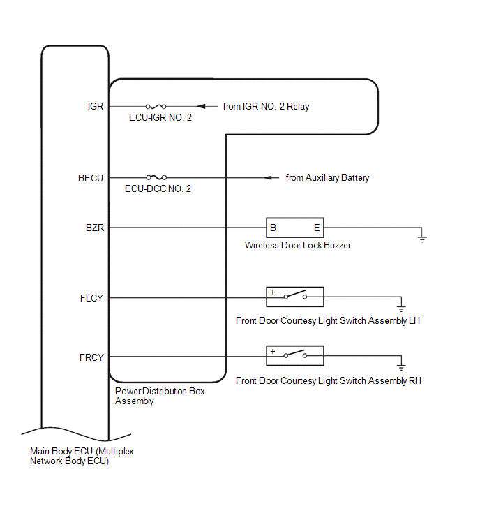
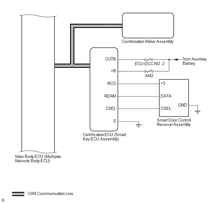
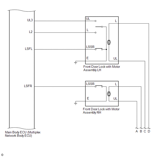
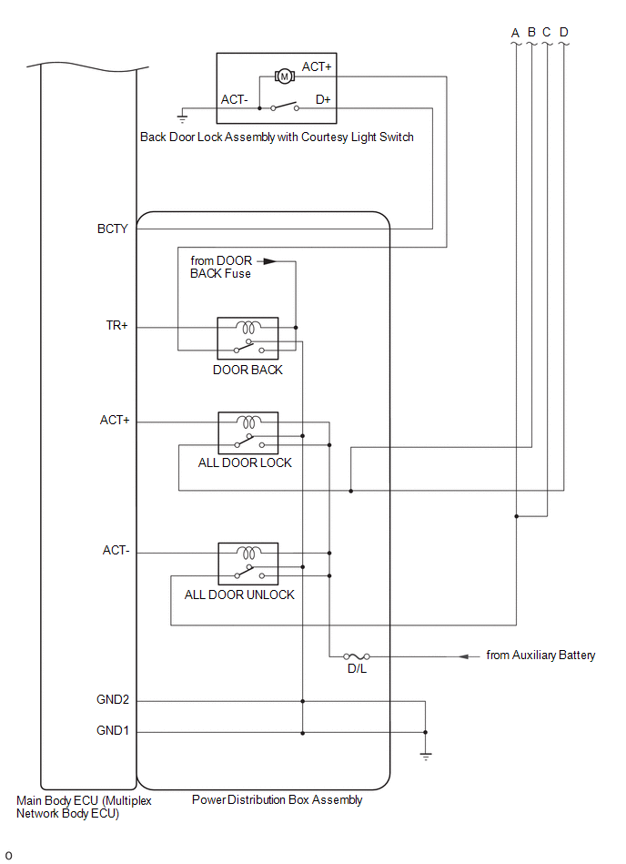
SYSTEM DIAGRAM
 Parts Location
PARTS LOCATION ILLUSTRATION
*1 HEADLIGHT ASSEMBLY RH - TURN SIGNAL LIGHT *2 SIDE TURN SIGNAL LIGHT ASSEMBLY RH *3 SIDE TURN SIGNAL LIGHT ASSEMBLY LH *4 REAR COMBINATION LIGHT ASSEMBLY RH - TURN SIGNAL LIGHT *5 REAR COMBINATION LIGHT ASSEMBLY LH - TURN SIGNAL LIGHT *6 HEADLIGHT ASSEMBLY LH - TURN SIGNAL LIGHT ILLUSTRATION
*1 FRONT DOOR LOCK WITH MOTOR ASSEMBLY RH *2 SMART DOOR CONTROL RECEIVER ASSEMBLY *3 FRONT DOOR COURTESY LIGHT SWITCH ASSEMBLY RH *4 FRONT DOOR COURTESY LIGHT SWITCH ASSEMBLY LH *5 FRONT DOOR LOCK WITH MOTOR ASSEMBLY LH *6 POWER DISTRIBUTION BOX ASSEMBLY - ECU-IGR NO...
 How To Proceed With Troubleshooting
CAUTION / NOTICE / HINT HINT:
Replace parts related to the wireless door lock and smart key system according to the inspection procedure.
If the wireless door lock and smart key system does not operate, first check the customize item and make sure that the wireless door lock and smart key system is not turned off...
Other information:
Toyota Yaris XP210 (2020-2026) Reapir and Service Manual: Front Wiper Rubber
C..
Toyota Yaris XP210 (2020-2026) Owner's Manual: Bright-Metal Maintenance
Use tar remover to remove road tar and insects. Never do this with a knife or similar tool. To prevent corrosion on bright-metal surfaces, apply wax or chrome preservative and rub it to a high luster. During cold weather or in coastal areas, cover bright-metal parts with a coating of wax or preservative heavier than usual...
Categories
- Manuals Home
- Toyota Yaris Owners Manual
- Toyota Yaris Service Manual
- Brake System Control Module "A" System Voltage System Voltage Low (C137BA2)
- Maintenance
- How to use USB mode
- New on site
- Most important about car
Keys

To use the auxiliary key, press the knob and pull out the auxiliary key from the smart key.

Copyright © 2026 www.toyaris4.com