Toyota Yaris: Sfi System / Fuel Pump "A" Control Circuit Short to Ground or Open (P062714)
DESCRIPTION
Refer to DTC P062712.
Click here

| DTC No. | Detection Item | DTC Detection Condition | Trouble Area | MIL | Note |
|---|---|---|---|---|---|
| P062714 | Fuel Pump "A" Control Circuit Short to Ground or Open | When the fuel pump control ECU operation duty ratio is 3 to 65%, the FPC terminal voltage is a certain value or less for 3 seconds or more (1 trip detection logic). |
| - | SAE: P0628 |
| DTC No. | Data List |
|---|---|
| P062714 | Fuel Pump Control Duty Ratio |
MONITOR DESCRIPTION
The ECM monitors the fuel pump control ECU operation signals.
When the output duty ratio of the operation signal from the ECM is 3 to 65% and the FPC terminal voltage is a certain value or less for 3 seconds or more, the ECM stores a DTC.
MONITOR STRATEGY
| Required Sensors/Components | Fuel pump control ECU |
| Frequency of Operation | Continuous |
CONFIRMATION DRIVING PATTERN
- Connect the GTS to the DLC3.
- Turn the ignition switch to ON.
- Turn the GTS on.
- Clear the DTCs (even if no DTCs are stored, perform the clear DTC procedure).
- Turn the ignition switch off and wait for at least 30 seconds.
- Turn the ignition switch to ON.
- Turn the GTS on.
- Start the engine and wait 10 seconds or more.
- Enter the following menus: Powertrain / Engine / Trouble Codes.
-
Read the pending DTCs.
HINT:
- If a pending DTC is output, the system is malfunctioning.
- If a pending DTC is not output, perform the following procedure.
- Enter the following menus: Powertrain / Engine / Utility / All Readiness.
- Input the DTC: P062714.
-
Check the DTC judgment result.
GTS Display
Description
NORMAL
- DTC judgment completed
- System normal
ABNORMAL
- DTC judgment completed
- System abnormal
INCOMPLETE
- DTC judgment not completed
- Perform driving pattern after confirming DTC enabling conditions
HINT:
- If the judgment result is NORMAL, the system is normal.
- If the judgment result is ABNORMAL, the system is malfunctioning.
- If the judgment result is INCOMPLETE, run the engine at an engine speed of 2500 rpm or more for 10 seconds or more and check the DTC judgment result again.
WIRING DIAGRAM
Refer to DTC P062712.
Click here

CAUTION / NOTICE / HINT
HINT:
Read Freeze Frame Data using the GTS. The ECM records vehicle and driving condition information as Freeze Frame Data the moment a DTC is stored. When troubleshooting, Freeze Frame Data can help determine if the vehicle was moving or stationary, if the engine was warmed up or not, if the air fuel ratio was lean or rich, and other data from the time the malfunction occurred.
PROCEDURE
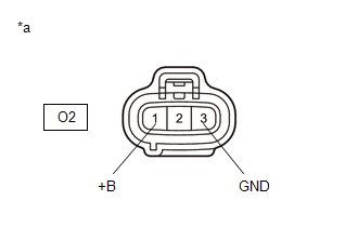
| 1. | CHECK HARNESS AND CONNECTOR (POWER SOURCE OF FUEL PUMP CONTROL ECU) |
(a) Disconnect the fuel pump control ECU connector.
(b) Turn the ignition switch to ON.
| (c) Measure the voltage according to the value(s) in the table below. Standard Voltage:
|
|
| NG |
 | GO TO STEP 4 |
|

| 2. | INSPECT ECM (FPC TERMINAL) |
(a) Disconnect the fuel pump control ECU connector.
(b) Operate the fuel pump control ECU using the Active Test function and measure the resistance according to the value(s) in the table below.
Powertrain > Engine > Active Test| Tester Display |
|---|
| Fuel Pump Single Phase Energization |
Standard Resistance:
| Tester Connection | GTS Operation | Specified Condition |
|---|---|---|
| O2-2 (FPC) - Body ground | Before Active Test → During Active Test | Before Active Test: Resistance is stable → During Active Test: Resistance fluctuates* |
HINT:
*: Using the Active Test, duty control of the transistors in the ECM will be performed. Due to the duty control, resistance of the FPC terminal will be unstable during the Active Test. If the resistance is stable before the Active Test and fluctuates while performing the Active Test, it can be determined that the transistor is operating. If the transistor does not operate during the Active Test, the ECM may be malfunctioning.
| OK |
 | REPLACE FUEL PUMP CONTROL ECU |
|

| 3. | CHECK HARNESS AND CONNECTOR (FUEL PUMP CONTROL ECU - ECM) |
(a) Disconnect the fuel pump control ECU connector.
(b) Disconnect the ECM connector.
(c) Measure the resistance according to the value(s) in the table below.
Standard Resistance:
| Tester Connection | Condition | Specified Condition |
|---|---|---|
| O2-2(FPC) - A106-6(FPC) | Always | Below 1 Ω |
| O2-2(FPC) or A106-6(FPC) - Body ground | Always | 10 kΩ or higher |
| OK |
 | REPLACE ECM |
| NG |
 | REPAIR OR REPLACE HARNESS OR CONNECTOR |
| 4. | CHECK HARNESS AND CONNECTOR (FUEL PUMP CONTROL ECU - BODY GROUND) |
(a) Disconnect the fuel pump control ECU connector.
(b) Measure the resistance according to the value(s) in the table below.
Standard Resistance:
| Tester Connection | Condition | Specified Condition |
|---|---|---|
| O2-3 (GND) - Body ground | Always | Below 1 Ω |
| NG |
 | REPAIR OR REPLACE HARNESS OR CONNECTOR |
|

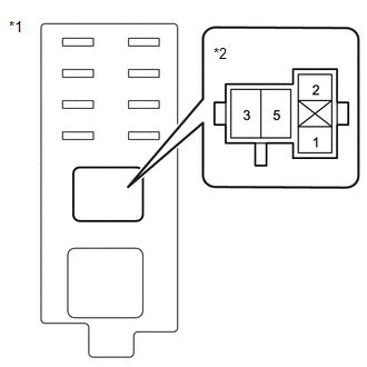
| 5. | INSPECT EFI-MAIN NO. 2 RELAY |
Click here

| NG |
 | REPLACE EFI-MAIN NO. 2 RELAY |
|

| 6. | CHECK TERMINAL VOLTAGE (POWER SOURCE OF EFI-MAIN NO. 2 RELAY) |
(a) Remove the EFI-MAIN NO. 2 relay from the No. 5 luggage room relay block assembly.
| (b) Measure the voltage according to the value(s) in the table below. Standard Voltage:
|
|
| NG |
 | REPAIR OR REPLACE HARNESS OR CONNECTOR (AUXILIARY BATTERY - EFI-MAIN NO. 2 RELAY) |
|

| 7. | CHECK HARNESS AND CONNECTOR (EFI-MAIN NO. 2 RELAY - BODY GROUND) |
(a) Remove the EFI-MAIN NO. 2 relay from the No. 5 luggage room relay block assembly.
(b) Measure the resistance according to the value(s) in the table below.
Standard Resistance:
| Tester Connection | Condition | Specified Condition |
|---|---|---|
| 1 (EFI-MAIN NO. 2 relay) - Body ground | Always | Below 1 Ω |
| NG |
 | REPAIR OR REPLACE HARNESS OR CONNECTOR |
|

| 8. | CHECK HARNESS AND CONNECTOR (FUEL PUMP CONTROL ECU - EFI-MAIN NO. 2 RELAY) |
(a) Disconnect the fuel pump control ECU connector.
(b) Remove the EFI-MAIN NO. 2 relay from the No. 5 luggage room relay block assembly.
(c) Measure the resistance according to the value(s) in the table below.
Standard Resistance:
| Tester Connection | Condition | Specified Condition |
|---|---|---|
| O2-1 (+B) - 5 (EFI-MAIN NO. 2 relay) | Always | Below 1 Ω |
| O2-1 (+B) or 5 (EFI-MAIN NO. 2 relay) - Body ground and other terminals | Always | 10 kΩ or higher |
| OK |
 | REPAIR OR REPLACE HARNESS OR CONNECTOR (EFI-MAIN NO. 1 RELAY - EFI-MAIN NO. 2 RELAY) |
| NG |
 | REPAIR OR REPLACE HARNESS OR CONNECTOR |
 Fuel Pump "A" Control Circuit Short to Battery (P062712)
DESCRIPTION The fuel pump control ECU performs PWM (Pulse Width Modulation) control to control the fuel pump (for low pressure side) speed steplessly over a wide range...
 VIN Not Programmed (P063051)
MONITOR DESCRIPTION DTC P063051 is stored when the Vehicle Identification Number (VIN) is not stored in the ECM or the stored VIN is not accurate. DTC No...
Other information:
Toyota Yaris XP210 (2020-2025) Reapir and Service Manual: Disassembly
DISASSEMBLY PROCEDURE 1. REMOVE WIRE HARNESS (a) Remove the 2 nuts and wire harness from the starter assembly. 2. REMOVE STARTER INRUSH CURRENT REDUCTION RELAY (a) Remove the bolt and wire harness from the starter inrush current reduction relay...
Toyota Yaris XP210 (2020-2025) Owner's Manual: Plastic Part Maintenance
When cleaning the plastic lenses of the lights, do not use gasoline, kerosene, rectified spirit, paint, thinner, highly acidic detergents, or strongly alkaline detergents. Otherwise, these chemical agents can discolor or damage the surfaces resulting in a significant loss in functionality...
Categories
- Manuals Home
- Toyota Yaris Owners Manual
- Toyota Yaris Service Manual
- G16e-gts (engine Mechanical)
- Auto Lock/Unlock Function
- Engine Start Function When Key Battery is Dead
- New on site
- Most important about car
Front Seat Belt Pretensioners
The front seat belt pretensioners are designed to deploy in moderate or severe frontal, near frontal collisions.
In addition, the pretensioners operate when a side collision or a rollover accident is detected. The pretensioners operate differently depending on what types of air bags are equipped. For more details about the seat belt pretensioner operation, refer to the SRS Air Bag Deployment Criteria.