Toyota Yaris: Sfi System / Barometric Pressure - Turbocharger / Supercharger Boost Sensor "A" Signal Compare Failure (P00CF62)
DESCRIPTION
At ignition switch to ON or during idling, the No. 2 turbo pressure sensor and the atmospheric pressure sensor built into the ECM are at atmospheric pressure and their outputs match.
| DTC No. | Detection Item | DTC Detection Condition | Trouble Area | MIL | Note |
|---|---|---|---|---|---|
| P00CF62 | Barometric Pressure - Turbocharger / Supercharger Boost Sensor "A" Signal Compare Failure | 15 kPa [2.18 psi] or greater difference between the atmospheric pressure values of the No. 2 turbo pressure sensor and the atmospheric pressure sensor (1 trip detection logic). |
| Comes on | SAE: P00CF |
MONITOR DESCRIPTION
At ignition switch to ON or during idling, the output values from the No. 2 turbo pressure sensor and the atmospheric pressure sensor built into the ECM are compared. If the difference in atmospheric pressure values is 15 kPa [2.18 psi] or greater, there may be a malfunction in the No. 2 turbo pressure sensor and atmospheric pressure sensor. In this case, the ECM stores a DTC.
MONITOR STRATEGY
| Required Sensors/Components | No. 2 turbo pressure sensor Atmospheric pressure sensor |
| Frequency of Operation | Continuous |
CONFIRMATION DRIVING PATTERN
- Connect the GTS to the DLC3.
- Turn the ignition switch to ON and turn the GTS on.
- Clear the DTCs (even if no DTCs are stored, perform the clear DTC procedure).
- Turn the ignition switch off and wait for at least 30 seconds.
- Turn the ignition switch to ON and turn the GTS on.
- Start the engine and wait 5 seconds or more.
- Enter the following menus: Powertrain / Engine / Trouble Codes.
-
Read the pending DTCs.
HINT:
- If a pending DTC is output, the system is malfunctioning.
- If a pending DTC is not output, perform the following procedure.
- Enter the following menus: Powertrain / Engine / Utility / All Readiness.
- Input the DTC: P00CF62.
-
Check the DTC judgment result.
GTS Display
Description
NORMAL
- DTC judgment completed
- System normal
ABNORMAL
- DTC judgment completed
- System abnormal
INCOMPLETE
- DTC judgment not completed
- Perform driving pattern after confirming DTC enabling conditions
HINT:
- If the judgment result shows NORMAL, the system is normal.
- If the judgment result shows ABNORMAL, the system has a malfunction.
WIRING DIAGRAM
Refer to DTC P023511.
Click here

CAUTION / NOTICE / HINT
HINT:
Read freeze frame data using the GTS. The ECM records vehicle and driving condition information as freeze frame data the moment a DTC is stored. When troubleshooting, freeze frame data can help determine if the vehicle was moving or stationary, if the engine was warmed up or not, if the air fuel ratio was lean or rich, and other data from the time the malfunction occurred.
PROCEDURE
| 1. | CHECK ANY OTHER DTCS OUTPUT (IN ADDITION TO DTC P00CF62) |
(a) Read the DTCs.
Powertrain > Engine > Trouble Codes| Result | Proceed to |
|---|---|
| P00CF62 is output | A |
| P00CF62 and P023400, P211900, P211904 or P211977 are output | |
| P00CF62 and P023400, P211900, P211904 or P211977 and other DTCs are output | B |
HINT:
If any DTCs other than P00CF62 and P023400, P211900, P211904 or P211977 are output, troubleshoot those DTCs first.
| B |
 | GO TO DTC CHART |
|

| 2. | READ VALUE USING GTS (BOOST PRESSURE SENSOR AND ATMOSPHERIC PRESSURE) |
(a) Enter the following menus.
Powertrain > Engine > Data List| Tester Display |
|---|
| Atmospheric Pressure |
| Boost Pressure Sensor |
(b) Compare Atmospheric Pressure and Boost Pressure Sensor or Boost Pressure Sensor2 in the Data List.
| Result | Proceed to |
|---|---|
| Difference between Atmospheric Pressure and Boost Pressure Sensor in the Data List exceeds 13 kPa [1.89 psi] | A |
| Other than above | B |
| B |
 | GO TO STEP 6 |
|

| 3. | READ VALUE USING GTS (BOOST PRESSURE SENSOR AND ATMOSPHERIC PRESSURE) |
(a) Enter the following menus.
Powertrain > Engine > Data List| Tester Display |
|---|
| Atmospheric Pressure |
| Boost Pressure Sensor |
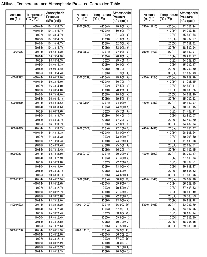
(b) Using the table, read the normal atmospheric pressure value for the applicable altitude and temperature.
HINT:
- Standard atmospheric pressure is approximately 101 kPa(abs) [14.65 psi(abs)].
- For every 100 m (328 ft.) increase in altitude, atmospheric pressure drops by approximately 1 kPa [0.15 psi]. This varies by weather.
(c) Compare the Atmospheric Pressure and Boost Pressure Sensor or Boost Pressure Sensor2 values in the Data List with the normal atmospheric value from the table.
| Result | Proceed to |
|---|---|
| Difference between (difference between Boost Pressure Sensor in the Data List and normal atmospheric pressure) and (difference between Atmospheric Pressure in the Data List and normal atmospheric pressure) is 4 kPa [0.58 psi] or greater | A |
| Other than above | B |
HINT:
- As the table below shows reference values only, use actual values for calculations.
- In Example 1, as the pressure difference is 4 kPa [0.58 psi] or higher, proceed to the next step.
- In Example 2, as the pressure difference is less than 4 kPa [0.58 psi], replace the ECM.
| Item | Example 1 | Example 2 | ||||
|---|---|---|---|---|---|---|
| Atmospheric pressure | Difference to normal atmospheric pressure | Difference between (difference between Boost Pressure Sensor in the Data List and normal atmospheric pressure) and (difference between Atmospheric Pressure in the Data List and normal atmospheric pressure) | Atmospheric pressure | Difference to normal atmospheric pressure | Difference between (difference between Boost Pressure Sensor in the Data List and normal atmospheric pressure) and (difference between Atmospheric Pressure in the Data List and normal atmospheric pressure) | |
| Normal atmospheric pressure | 100 kPa(abs) [15.5 psi(abs)] | - | 6 kPa [0.87 psi] | 100 kPa(abs) [15.5 psi(abs)] | - | 2 kPa [0.29 psi] |
| Boost Pressure Sensor or Boost Pressure Sensor2 in the Data List | 110 kPa(abs) [15.95 psi(abs)] | 10 kPa [1.45 psi] | 108 kPa(abs) [15.66 psi(abs)] | 8 kPa [1.16 psi] | ||
| Atmospheric Pressure in the Data List | 96 kPa(abs) [13.92 psi(abs)] | 4 kPa [0.58 psi] | 94 kPa(abs) [13.63 psi(abs)] | 6 kPa [0.87 psi] | ||
| B |
 | REPLACE ECM |
|

| 4. | CHECK HARNESS AND CONNECTOR |
(a) Disconnect the No. 2 turbo pressure sensor connector.
(b) Turn the ignition switch to ON.
| (c) Measure the voltage according to the value(s) in the table below. Standard Voltage:
|
|
(d) Turn the ignition switch off and wait for at least 30 seconds.
(e) Measure the resistance according to the value(s) in the table below.
Standard Resistance:
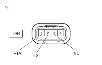
| Tester Connection | Condition | Specified Condition |
|---|---|---|
| D94-3(VC) - D94-1(PTA) | Ignition switch off | 171 to 189 kΩ |
| D94-2(E2) - Body ground | Always | Below 1 Ω |
| OK |
 | REPLACE NO. 2 TURBO PRESSURE SENSOR |
|

| 5. | CHECK HARNESS AND CONNECTOR (NO. 2 TURBO PRESSURE SENSOR - ECM) |
(a) Disconnect the No. 2 turbo pressure sensor connector.
(b) Disconnect the ECM connector.
(c) Measure the resistance according to the value(s) in the table below.
Standard Resistance:
| Tester Connection | Condition | Specified Condition |
|---|---|---|
| D94-3(VC) - D104-80(VPTA) | Always | Below 1 Ω |
| D94-2(E2) - D104-79(EPTA) | Always | Below 1 Ω |
| D94-1(PTA) - D104-103(PTA) | Always | Below 1 Ω |
| D94-3(VC) or D104-80(VPTA) - Body ground and other terminals | Always | 10 kΩ or higher |
| D94-1(PTA) or D104-103(PTA) - Body ground and other terminals | Always | 10 kΩ or higher |
| OK |
 | REPLACE ECM |
| NG |
 | REPAIR OR REPLACE HARNESS OR CONNECTOR |
| 6. | CHECK INTAKE SYSTEM |
(a) Check that there is no air suction or blockage at any points in the intake system.
Click here

OK:
No air suction or blockage.
HINT:
Perform "Inspection After Repair" after repairing or replacing the intake system.
Click here

| NG |
 | REPAIR OR REPLACE INTAKE SYSTEM |
|

| 7. | CLEAR DTC |
(a) Clear the DTCs.
Powertrain > Engine > Clear DTCs(b) Turn the ignition switch off and wait for at least 30 seconds.
|

| 8. | CHECK WHETHER DTC OUTPUT RECURS (DTC P00CF62) |
(a) Drive the vehicle in accordance with the driving pattern described in Confirmation Driving Pattern.
(b) Enter the following menus.
Powertrain > Engine > Utility| Tester Display |
|---|
| All Readiness |
(c) Input the DTC: P00CF62
(d) Check the DTC judgment result.
| Result | Proceed to |
|---|---|
| NORMAL (DTCs are not output) | A |
| ABNORMAL (P00CF62 is output) | B |
| A |
 | END |
| B |
 | REPLACE ECM |
 Low Pressure Fuel System Pressure - Too High (P008B00)
DESCRIPTION Refer to DTC P008A00. Click here
DTC No. Detection Item DTC Detection Condition Trouble Area MIL Note P008B00 Low Pressure Fuel System Pressure - Too High The actual fuel pressure (for low pressure side) value is higher than target fuel pressure (for low pressure side) by 200 kPa [29 psi] or more (1 trip detection logic)...
 Mass or Volume Air Flow Sensor "A" Circuit Short to Battery (P010012,P010014)
DESCRIPTION The mass air flow meter sub-assembly is a sensor that measures the intake air volume using the following built-in components:
By-pass passage (allows some of the intake air to flow past a silicon chip sensor)
Silicon chip sensor (uses a heater control bridge circuit and temperature sensor bridge circuit to detect the difference in the temperature of the intake air that passes the sensors positioned before and after the heater)...
Other information:
Toyota Yaris XP210 (2020-2025) Reapir and Service Manual: STA Signal Circuit
DESCRIPTION While the engine is being cranked, a starter operation request signal is sent to terminal STA of the ECM. HINT: If there is an open in the STA circuit of the ECM, stop and start control will be prohibited after the third time the engine is started by stop and start control...
Toyota Yaris XP210 (2020-2025) Reapir and Service Manual: Inspection
INSPECTION PROCEDURE 1. INSPECT PROPELLER SHAFT WITH CENTER BEARING ASSEMBLY (a) Using a dial indicator, measure the propeller shaft runout for the front side. Maximum Runout: 0.4 mm (0.0157 in.) If the runout is more than the maximum, replace the propeller shaft with center bearing assembly...
Categories
- Manuals Home
- Toyota Yaris Owners Manual
- Toyota Yaris Service Manual
- Power Integration No.1 System Missing Message (B235287,B235587,B235787-B235987)
- Key Battery Replacement
- Battery Monitor Module General Electrical Failure (P058A01)
- New on site
- Most important about car
Turning the Engine Off
Stop the vehicle completely. Manual transaxle: Shift into neutral and set the parking brake.Automatic transaxle: Shift the selector lever to the P position and set the parking brake.
Press the push button start to turn off the engine. The ignition position is off.