Toyota Yaris: Stop And Start System / STA Signal Circuit
DESCRIPTION
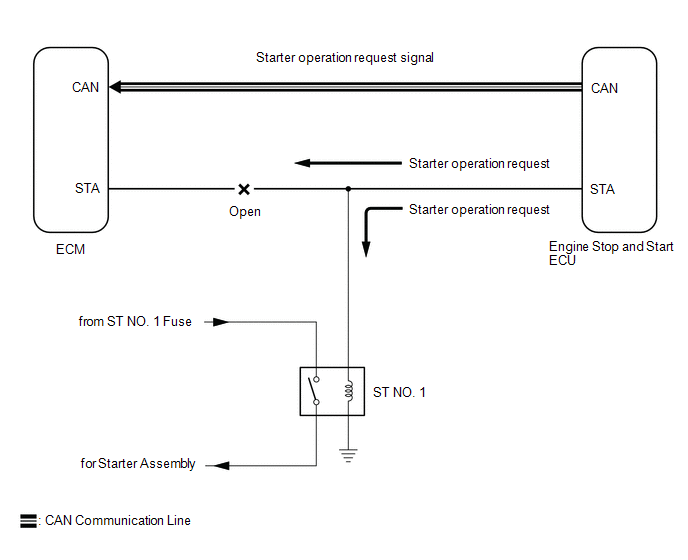
While the engine is being cranked, a starter operation request signal is sent to terminal STA of the ECM.
HINT:
If there is an open in the STA circuit of the ECM, stop and start control will be prohibited after the third time the engine is started by stop and start control.
- Stop and start control will be prohibited until the ignition switch is turned off.
- The MIL will not illuminate.
- If there is an open in the STA circuit of the ECM, the engine can still be started using the ignition switch, as the ECM also receives the starter operation request signal from the engine stop and start ECU via CAN communication. (Stop and start control is prohibited as the reliability of the signal sent via CAN communication cannot be assured while the voltage drops during operation of the starter assembly.)
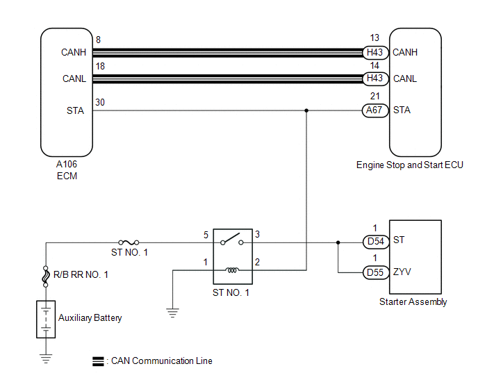
WIRING DIAGRAM
PROCEDURE
| 1. | READ VALUE USING GTS (STARTER SW) |
| Tester Display |
|---|
| Starter SW |
(a) Read the values displayed on the GTS when the ignition switch is ON and on (START).
OK:
| GTS Display | Switch Condition | Normal Condition |
|---|---|---|
| Starter SW | Ignition switch ON | OFF |
| Ignition switch START | ON |
| OK |
 | PROCEED TO NEXT SUSPECTED AREA SHOWN IN PROBLEM SYMPTOMS TABLE |
|

| 2. | CHECK HARNESS AND CONNECTOR (ECM - ST NO. 1 RELAY) |
(a) Disconnect the A67 engine stop and start ECU connector.
(b) Disconnect the A106 ECM connector.
(c) Remove the ST NO. 1 relay from the No. 1 engine room relay block and No. 1 junction block assembly.
(d) Measure the resistance according to the value(s) in the table below.
Standard Resistance:
| Tester Connection | Condition | Specified Condition |
|---|---|---|
| A106-30 (STA) - ST NO. 1 relay terminal 2 | Always | Below 1 Ω |
| OK |
 | PROCEED TO NEXT SUSPECTED AREA SHOWN IN PROBLEM SYMPTOMS TABLE |
| NG |
 | REPAIR OR REPLACE HARNESS OR CONNECTOR |
 Failure to Restart from IG-ON Engine Stall
DESCRIPTION
This is the troubleshooting procedure for situations where the engine does not restart when attempting to restart it after either a failed engine start occurred under stop and start system control, or a mis-operation during vehicle takeoff resulted in an engine stall...
 Stop And Start System Cancel Switch Assembly
ComponentsCOMPONENTS ILLUSTRATION
*1 ECO RUN CANCEL SWITCH ASSEMBLY (COMBINATION SWITCH ASSEMBLY) - - RemovalREMOVAL PROCEDURE 1. REMOVE ECO RUN CANCEL SWITCH ASSEMBLY (COMBINATION SWITCH ASSEMBLY) Click here
InspectionINSPECTION PROCEDURE 1...
Other information:
Toyota Yaris XP210 (2020-2026) Owner's Manual: Front Passenger’s Seat Child-Restraint System Installation
Make sure the ignition is switched off. Slide the seat as far back as possible. Remove the head restraint. Place the child-restraint system on the seat without putting your weight on the seat and fasten the seat belt. See the manufacturer’s instructions on the child-restraint system for belt routing instructions...
Toyota Yaris XP210 (2020-2026) Reapir and Service Manual: Driver Side Power Window Auto Up / Down Function does not Operate with Power Window Master Switch
DESCRIPTION If the manual up and down functions operate normally but the auto up and down functions do not, the power window control system may be in fail-safe mode. If power window initialization has not been performed, the auto up and down functions will not operate...
Categories
- Manuals Home
- Toyota Yaris Owners Manual
- Toyota Yaris Service Manual
- Engine Start Function When Key Battery is Dead
- Battery Monitor Module General Electrical Failure (P058A01)
- How to connect USB port/Auxiliary jack
- New on site
- Most important about car
Supplemental Restraint System (SRS) Precautions
The front and side supplemental restraint systems (SRS) include different types of air bags. Please verify the different types of air bags which are equipped on your vehicle by locating the “SRS AIRBAG” location indicators. These indicators are visible in the area where the air bags are installed.
The air bags are installed in the following locations:
The steering wheel hub (driver air bag) The front passenger dashboard (front passenger air bag) The outboard sides of the front seatbacks (side air bags) The front and rear window pillars, and the roof edge along both sides (curtain air bags)