Toyota Yaris: Sfi System / Low Pressure Fuel System Pressure - Too High (P008B00)
DESCRIPTION
Refer to DTC P008A00.
Click here

| DTC No. | Detection Item | DTC Detection Condition | Trouble Area | MIL | Note |
|---|---|---|---|---|---|
| P008B00 | Low Pressure Fuel System Pressure - Too High | The actual fuel pressure (for low pressure side) value is higher than target fuel pressure (for low pressure side) by 200 kPa [29 psi] or more (1 trip detection logic). |
| - | SAE: P008B |
MONITOR DESCRIPTION
If the fuel pressure (for low pressure side) increases despite a decrease request signal being sent to the fuel pump control ECU by the ECM, the ECM will store this DTC.
MONITOR STRATEGY
| Frequency of Operation | Continuous |
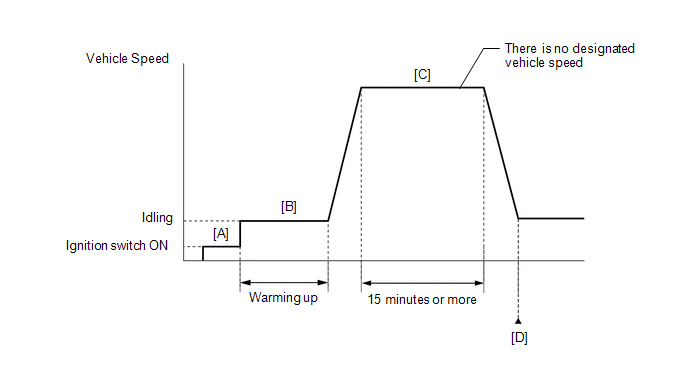
CONFIRMATION DRIVING PATTERN
- Connect the GTS to the DLC3.
- Turn the ignition switch to ON.
- Turn the GTS on.
- Clear the DTCs (even if no DTCs are stored, perform the clear DTC procedure).
- Turn the ignition switch off and wait for at least 30 seconds.
- Turn the ignition switch to ON [A].
- Turn the GTS on.
- Start the engine and warm it up until the engine coolant temperature reaches 75°C (167°F) or higher [B].
-
Drive the vehicle for 15 minutes or more [C].
CAUTION:
When performing the confirmation driving pattern, obey all speed limits and traffic laws.
- Enter the following menus: Powertrain / Engine / Trouble Codes [D].
-
Read the pending DTCs.
HINT:
- If a pending DTC is output, the system is malfunctioning.
- If a pending DTC is not output, perform the following procedure.
- Enter the following menus: Powertrain / Engine / Utility / All Readiness.
- Input the DTC: P008B00.
-
Check the DTC judgment result.
GTS Display
Description
NORMAL
- DTC judgment completed
- System normal
ABNORMAL
- DTC judgment completed
- System abnormal
INCOMPLETE
- DTC judgment not completed
- Perform driving pattern after confirming DTC enabling conditions
HINT:
- If the judgment result is NORMAL, the system is normal.
- If the judgment result is ABNORMAL, the system has a malfunction.
- If the judgment result is INCOMPLETE, perform steps [B] through [D] again.
CAUTION / NOTICE / HINT
HINT:
Read Freeze Frame Data using the GTS. The ECM records vehicle and driving condition information as Freeze Frame Data the moment a DTC is stored. When troubleshooting, Freeze Frame Data can help determine if the vehicle was moving or stationary, if the engine was warmed up or not, if the air fuel ratio was lean or rich, and other data from the time the malfunction occurred.
PROCEDURE
| 1. | CHECK OTHER DTCS OUTPUT (IN ADDITION TO DTC P008B00) |
(a) Read the DTCs.
Powertrain > Engine > Trouble Codes| Result | Proceed to |
|---|---|
| P008B00 is output | A |
| P008B00 and other DTCs are output | B |
HINT:
If any DTCs other than P008B00 are output, troubleshoot those DTCs first.
| B |
 | GO TO DTC CHART |
|

| 2. | READ VALUE USING GTS (FUEL PRESSURE (LOW) / FUEL PRESSURE 2) |
(a) Start the engine.
(b) Enter the following menus.
Powertrain > Engine > Data List| Tester Display |
|---|
| Fuel Pressure (Low) / Fuel Pressure 2 |
(c) Record the Fuel Pressure (Low) / Fuel Pressure 2 value.
(d) Turn the ignition switch off.
(e) Discharge the fuel pressure.
(1) Remove the EFI-MAIN NO. 2 fuse from the No. 5 luggage room relay block assembly.
(2) Start the engine.
(3) After the engine has stopped on its own, turn the ignition switch off.
HINT:
If the engine does not stop naturally, perform direct injection by racing the engine to reduce the fuel pressure [Fuel Pressure (High)] and stop the engine.
(4) Crank the engine again and make sure that the engine does not start.
(5) Install the EFI-MAIN NO. 2 fuse.
(f) Enter the following menus.
Powertrain > Engine > Data List| Tester Display |
|---|
| Fuel Pressure (Low) / Fuel Pressure 2 |
(g) Compare the Fuel Pressure (Low) / Fuel Pressure 2 value recorded with the engine running to the Fuel Pressure (Low) / Fuel Pressure 2 value currently shown on the GTS.
| Result | Proceed to |
|---|---|
| Fuel Pressure (Low) / Fuel Pressure 2 value drops | A |
| Fuel Pressure (Low) / Fuel Pressure 2 value is maintained | B |
HINT:
Perform "Inspection After Repair" after replacing the No. 2 fuel pressure sensor (for low pressure side).
Click here

| B |
 | REPLACE NO. 2 FUEL PRESSURE SENSOR (FOR LOW PRESSURE SIDE) |
|

| 3. | PERFORM ACTIVE TEST USING GTS (CONTROL THE FUEL PUMP DUTY RATIO (BRUSHLESS)) |
(a) Install the fuel pressure gauge (for low pressure line of low pressure side).
Click here

(b) Enter the following menus.
Powertrain > Engine > Active Test| Active Test Display |
|---|
| Control the Fuel Pump Duty Ratio (Brushless) |
| Data List Display |
|---|
| Target Fuel Pressure (Low) / Target Fuel Pressure 2 |
(c) Compare the values in the Data List using the GTS and the fuel pressure gauge when the Active Test was performed.
Standard:
| GTS Operation | Standard |
|---|---|
| Low | Data List value and fuel pressure gauge are within +/-50 kPa of each other |
| High |
HINT:
Perform "Inspection After Repair" after replacing the No. 2 fuel pressure sensor (for low pressure side).
Click here

| NG |
 | REPLACE NO. 2 FUEL PRESSURE SENSOR (FOR LOW PRESSURE SIDE) |
|

| 4. | PERFORM ACTIVE TEST USING GTS (CONTROL THE FUEL PUMP DUTY RATIO (BRUSHLESS)) |
(a) Install the fuel pressure gauge (for low pressure line of low pressure side).
Click here

(b) Enter the following menus.
Powertrain > Engine > Active Test| Active Test Display |
|---|
| Control the Fuel Pump Duty Ratio (Brushless) |
| Data List Display |
|---|
| Target Fuel Pressure (Low) / Target Fuel Pressure 2 |
(c) Read the values on the Data List and the fuel pressure gauge when the Active Test was performed.
| GTS Operation | Fuel Pressure (Low) / Fuel Pressure 2 | Fuel Pressure Gauge | Proceed to |
|---|---|---|---|
| Low | Below 600 kPag | Below 600 kPa (6.1 kgf/cm2, 87 psi) | A |
| 600 kPag or higher | 600 kPa (6.1 kgf/cm2, 87 psi) or higher | B |
| B |
 | REPLACE FUEL PUMP CONTROL ECU |
|

| 5. | CLEAR DTC |
(a) Clear the DTCs.
Powertrain > Engine > Clear DTCs(b) Turn the ignition switch off and wait for at least 30 seconds.
|

| 6. | CHECK WHETHER DTC OUTPUT RECURS (DTC P008B00) |
(a) Drive the vehicle in accordance with the driving pattern described in Confirmation Driving Pattern.
(b) Enter the following menus.
Powertrain > Engine > Utility| Tester Display |
|---|
| All Readiness |
(c) Input the DTC: P008B00.
(d) Check the DTC judgment result.
| Result | Proceed to |
|---|---|
| NORMAL (DTCs are not output) | A |
| ABNORMAL (P008B00 is output) | B |
| A |
 | CHECK FOR INTERMITTENT PROBLEMS |
| B |
 | REPLACE ECM |
 Low Pressure Fuel System Pressure - Too Low (P008A00)
DESCRIPTION In order to supply the optimal fuel pressure according to the driving conditions and usage environment, the variable fuel system sends a drive signal from the ECM to the fuel pump control ECU, steplessly performing variable control of the fuel pump (for low pressure side) and receiving feedback about the fuel pressure (for low pressure side) from the No...
 Barometric Pressure - Turbocharger / Supercharger Boost Sensor "A" Signal Compare Failure (P00CF62)
DESCRIPTION At ignition switch to ON or during idling, the No. 2 turbo pressure sensor and the atmospheric pressure sensor built into the ECM are at atmospheric pressure and their outputs match...
Other information:
Toyota Yaris XP210 (2020-2026) Reapir and Service Manual: Road Test
ROAD TEST ROAD TEST (a) Check for DTCs. Click here Powertrain > Engine > Trouble Codes HINT: When DTCs are output, perform troubleshooting for each DTC. Click here (b) Turn the iMT switch on and off and check that the iMT indicator light illuminates and turns off...
Toyota Yaris XP210 (2020-2026) Reapir and Service Manual: Power Integration No.1 System Internal Failure (B235204)
DESCRIPTION This DTC is output when the semiconductor power integration ECU detects a Internal circuit error. DTC No. Detection Item DTC Detection Condition Trouble Area B235204 Power Integration No.1 System Internal Failure Microcomputer abnormality AD circuit trouble Semiconductor power integration ECU WIRING DIAGRAM Click here CAUTION / NOTICE / HINT NOTICE: When using the GTS with the ignition switch off to troubleshoot: Connect the GTS to the vehicle, and turn a courtesy switch on and off at 1...
Categories
- Manuals Home
- Toyota Yaris Owners Manual
- Toyota Yaris Service Manual
- Auto Lock/Unlock Function
- Fuel Gauge
- G16e-gts (engine Mechanical)
- New on site
- Most important about car
Supplemental Restraint System (SRS) Precautions
The front and side supplemental restraint systems (SRS) include different types of air bags. Please verify the different types of air bags which are equipped on your vehicle by locating the “SRS AIRBAG” location indicators. These indicators are visible in the area where the air bags are installed.
The air bags are installed in the following locations:
The steering wheel hub (driver air bag) The front passenger dashboard (front passenger air bag) The outboard sides of the front seatbacks (side air bags) The front and rear window pillars, and the roof edge along both sides (curtain air bags)