
Toyota Yaris: Lighting System / System Diagram
Toyota Yaris XP210 (2020-2026) Reapir and Service Manual / Vehicle Exterior / Lighting (ext) / Lighting System / System Diagram
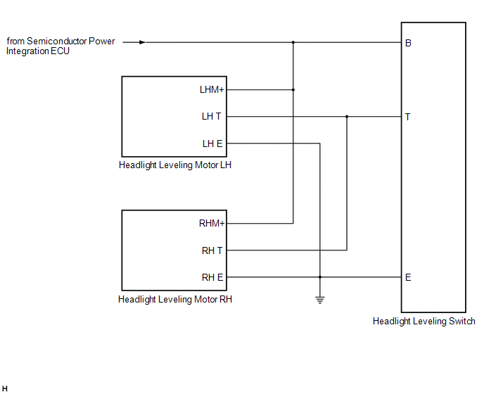
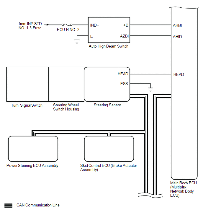
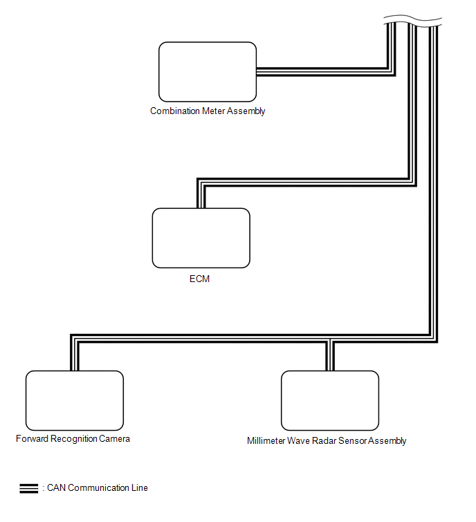
SYSTEM DIAGRAM
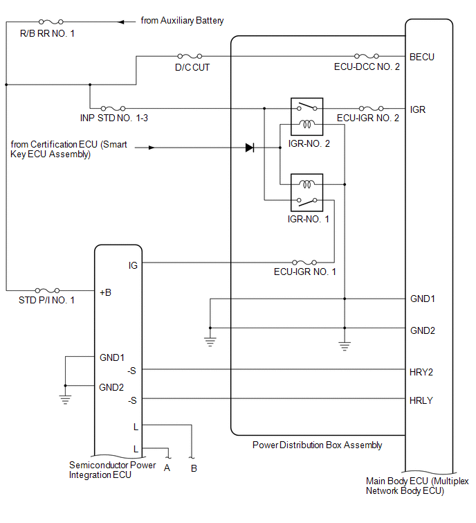
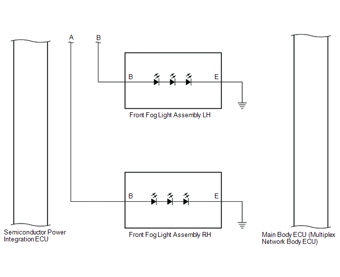
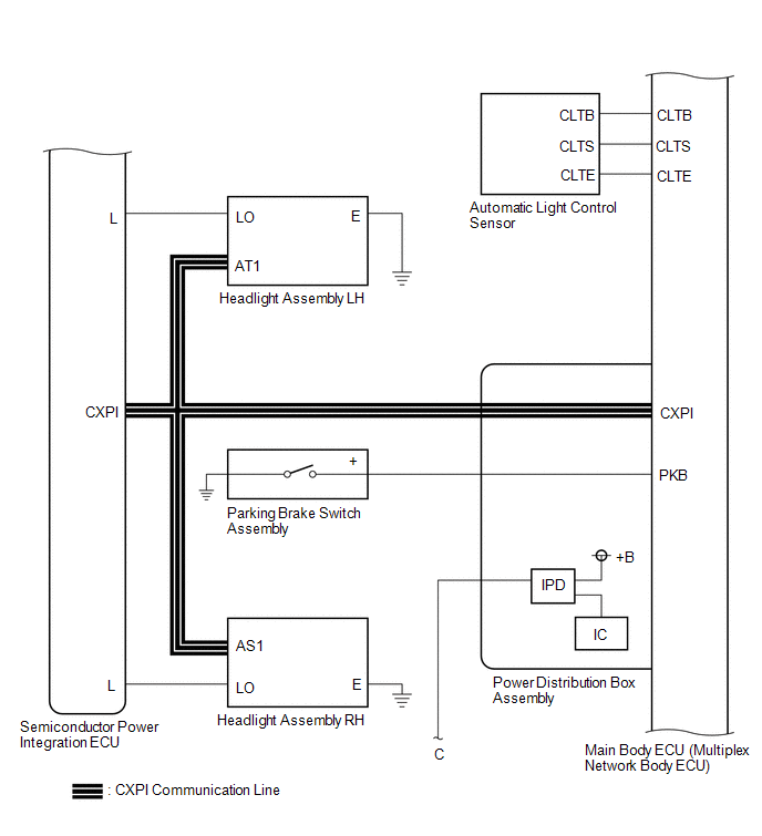
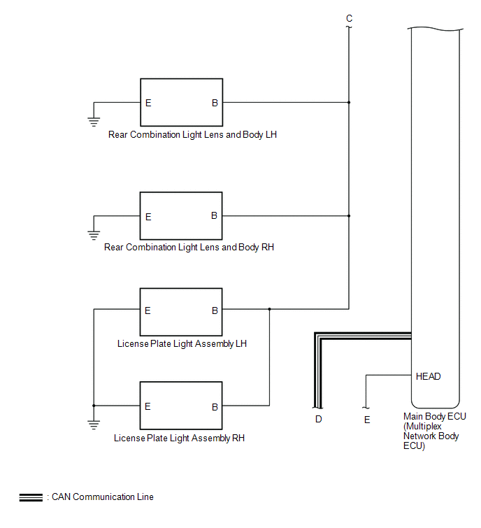
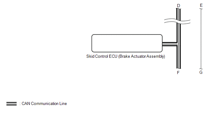
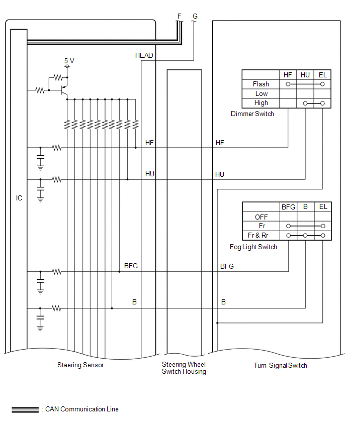
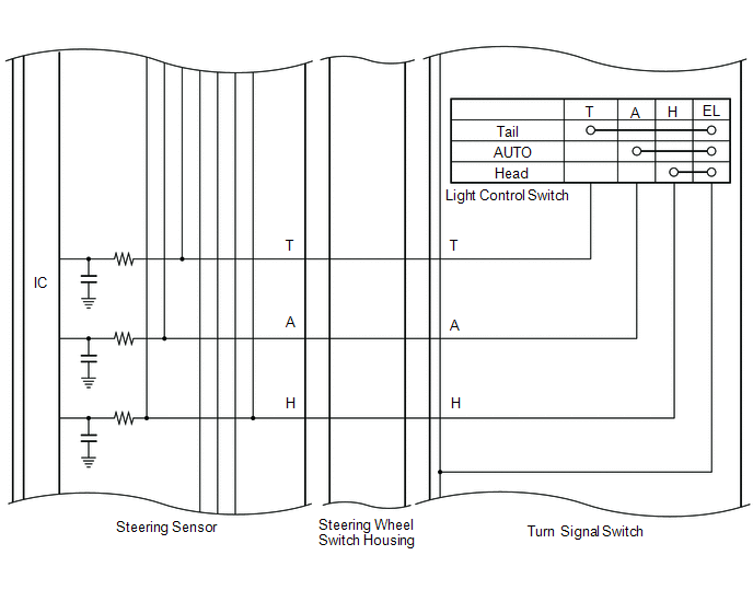
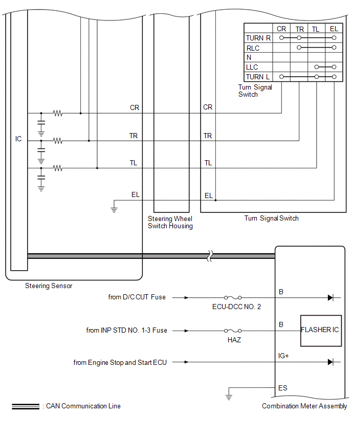
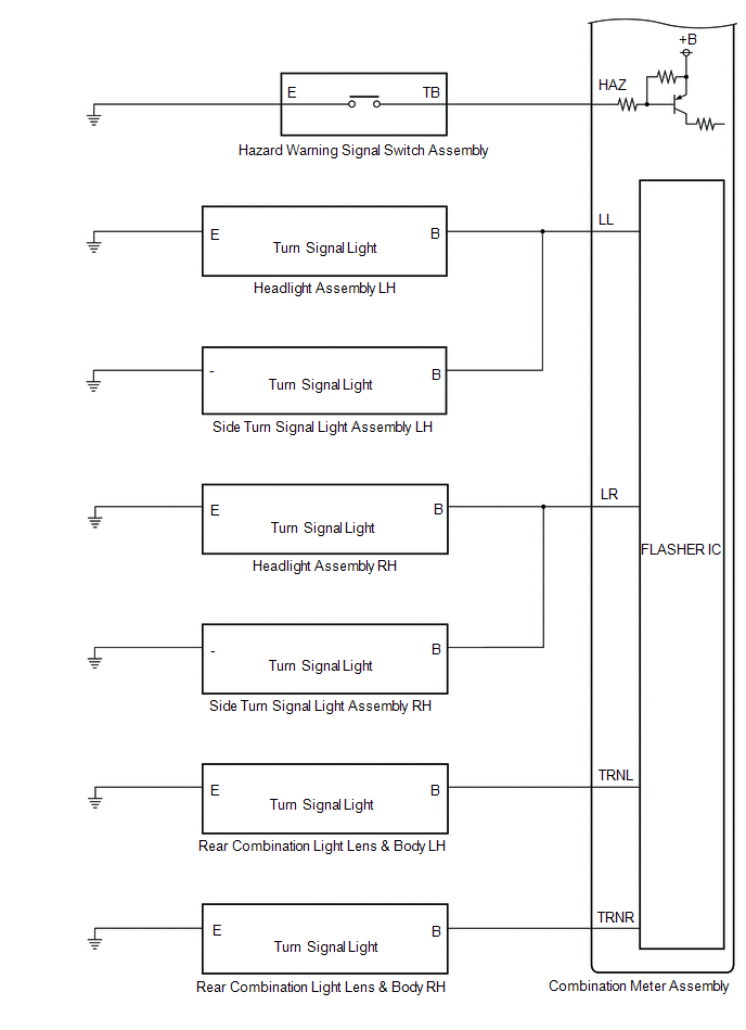
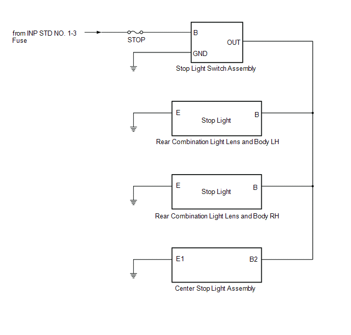
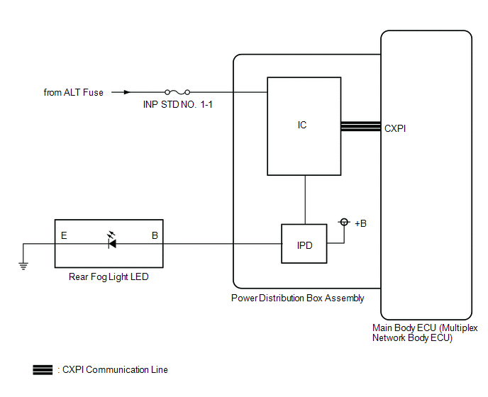
MANUAL LEVELING SYSTEM
AUTOMATIC HIGH BEAM SYSTEM (w/ Toyota Safety Sense)
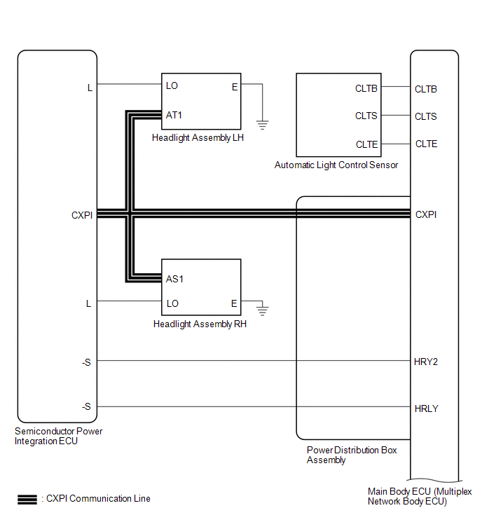
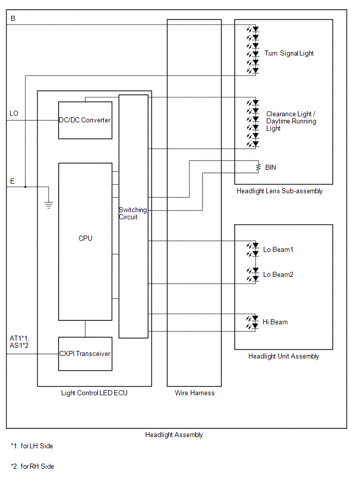
HEADLIGHT ASSEMBLY CIRCUIT
 Parts Location
PARTS LOCATION ILLUSTRATION
*A w/ Toyota Safety Sense - - *1 SIDE TURN SIGNAL LIGHT ASSEMBLY LH *2 SIDE TURN SIGNAL LIGHT ASSEMBLY RH *3 HEADLIGHT ASSEMBLY LH *4 HEADLIGHT ASSEMBLY RH *5 HEADLIGHT LENS SUB-ASSEMBLY LH *6 HEADLIGHT LENS SUB-ASSEMBLY RH *7 HEADLIGHT UNIT ASSEMBLY LH *8 HEADLIGHT UNIT ASSEMBLY RH *9 LIGHT CONTROL LED ECU LH *10 LIGHT CONTROL LED ECU RH *11 HEADLIGHT LEVELING MOTOR LH *12 HEADLIGHT LEVELING MOTOR RH *13 HEADLIGHT HOUSING SUB-ASSEMBLY LH (WIRE HARNESS LH) *14 HEADLIGHT HOUSING SUB-ASSEMBLY RH (WIRE HARNESS RH) *15 FOG LIGHT ASSEMBLY LH *16 FOG LIGHT ASSEMBLY RH *17 FORWARD RECOGNITION CAMERA *18 MILLIMETER WAVE RADAR SENSOR ASSEMBLY *19 ECM *20 POWER STEERING ECU ASSEMBLY *21 SKID CONTROL ECU (BRAKE ACTUATOR ASSEMBLY) *22 NO...
 How To Proceed With Troubleshooting
CAUTION / NOTICE / HINT HINT:
Use the following procedure to troubleshoot the lighting system.
*: Use the GTS.
PROCEDURE 1. VEHICLE BROUGHT TO WORKSHOP
NEXT
2...
Other information:
Toyota Yaris XP210 (2020-2026) Reapir and Service Manual: Left Front Wheel Speed Sensor Circuit Short to Battery (C050012)
DESCRIPTION Refer to DTC C05001F. Click here DTC No. Detection Item DTC Detection Condition Trouble Area DTC Output from C050012 Left Front Wheel Speed Sensor Circuit Short to Battery The speed sensor short signal is ON continuously for 0...
Toyota Yaris XP210 (2020-2026) Reapir and Service Manual: Removal
REMOVAL CAUTION / NOTICE / HINT The necessary procedures (adjustment, calibration, initialization, or registration) that must be performed after parts are removed and installed, or replaced during the front door with motor lock assembly removal/installation are shown below...
Categories
- Manuals Home
- Toyota Yaris Owners Manual
- Toyota Yaris Service Manual
- Battery Monitor Module General Electrical Failure (P058A01)
- How to connect USB port/Auxiliary jack
- G16e-gts (engine Mechanical)
- New on site
- Most important about car
Refueling
Before refueling, close all the doors, windows, and the liftgate/trunk lid, and switch the ignition OFF.
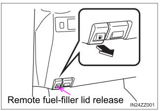
To open the fuel-filler lid, pull the remote fuel-filler lid release.

Copyright © 2026 www.toyaris4.com