Toyota Yaris: Front Seat Inner Belt Assembly / Inspection
INSPECTION
PROCEDURE
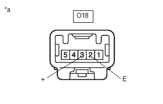
1. INSPECT FRONT SEAT INNER BELT ASSEMBLY (for Driver Side)
(a) Check the resistance.
| (1) Measure the resistance according to the value(s) in the table below. Standard Resistance:
|
| ||||||||||||||||
2. INSPECT FRONT SEAT INNER BELT ASSEMBLY (for Front Passenger Side)
(a) Check the resistance (seat belt tension reducer system).
| (1) Measure the resistance according to the value(s) in the table below. Standard Resistance:
|
| ||||||||||||||||
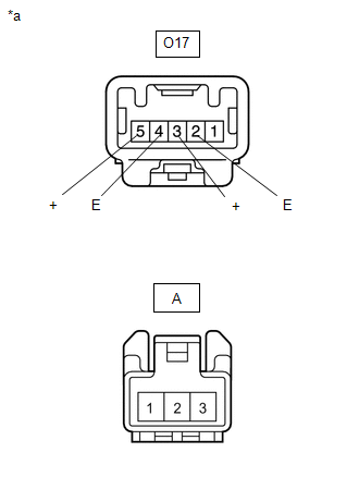
(b) Check the resistance (seat belt warning switch).
(1) Measure the resistance according to the value(s) in the table below.
Standard Resistance:
| Tester Connection | Condition | Specified Condition |
|---|---|---|
| If the result is not as specified, replace the front seat inner belt assembly. | ||
| O17-5(+) - A-1 | Always | Below 1 Ω |
| O17-4(E) - A-3 | Always | Below 1 Ω |
 Removal
REMOVAL CAUTION / NOTICE / HINT CAUTION: Be sure to read Precaution thoroughly before servicing.
Click here
NOTICE: If a front seat airbag assembly has been deployed, replace the front seat airbag assembly, front seatback frame sub-assembly, separate type front seatback pad, separate type front seatback cover and front seatback pad with cover with the necessary parts in accordance with the extent of the collision damage...
 Installation
INSTALLATION CAUTION / NOTICE / HINT HINT:
Use the same procedure for the driver side and front passenger side.
The procedure listed below is for the driver side...
Other information:
Toyota Yaris XP210 (2020-2026) Reapir and Service Manual: Removal
REMOVAL PROCEDURE 1. RECOVER REFRIGERANT FROM REFRIGERATION SYSTEM Click here 2. REMOVE NO. 1 ENGINE UNDER COVER ASSEMBLY Click here 3. REMOVE FAN AND GENERATOR V BELT Click here 4. DISCONNECT SUCTION HOSE SUB-ASSEMBLY (a) Remove the bolt and disconnect the suction hose sub-assembly from the compressor with pulley assembly...
Toyota Yaris XP210 (2020-2026) Reapir and Service Manual: Cruise SET Indicator Light Circuit
DESCRIPTION The ECM illuminates the cruise SET indicator by sending request signals to the combination meter assembly via CAN communication. The cruise SET indicator illuminates when the dynamic radar cruise control system is controlling vehicle speed...
Categories
- Manuals Home
- Toyota Yaris Owners Manual
- Toyota Yaris Service Manual
- Diagnostic Trouble Code Chart
- Key Battery Replacement
- Battery Monitor Module General Electrical Failure (P058A01)
- New on site
- Most important about car
Break-In Period
No special break-in is necessary, but a few precautions in the first 600 miles (1,000 km) may add to the performance, economy, and life of the vehicle.
Do not race the engine. Do not maintain one constant speed, either slow or fast, for a long period of time. Do not drive constantly at full-throttle or high engine rpm for extended periods of time. Avoid unnecessary hard stops. Avoid full-throttle starts.