Toyota Yaris: Front Seat Inner Belt Assembly / Removal
REMOVAL
CAUTION / NOTICE / HINT
CAUTION:
Be sure to read Precaution thoroughly before servicing.
Click here

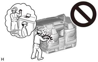
NOTICE:
If a front seat airbag assembly has been deployed, replace the front seat airbag assembly, front seatback frame sub-assembly, separate type front seatback pad, separate type front seatback cover and front seatback pad with cover with the necessary parts in accordance with the extent of the collision damage.
Click here

HINT:
-
When the cable is disconnected/reconnected to the auxiliary battery terminal, systems temporarily stop operating. However, each system has a function that completes learning the first time the system is used.
-
Learning completes when vehicle is driven
Effect/Inoperative Function When Necessary Procedures are not Performed
Necessary Procedures
Link
Lane tracing assist system
Drive the vehicle straight ahead at 35 km/h (22 mph) or more for 5 seconds or more.

Pre-collision system
Stop and start system
Drive the vehicle until stop and start control is permitted (approximately 5 to 60 minutes)

-
Learning completes when vehicle is operated normally
Effect/Inoperative Function When Necessary Procedures are not Performed
Necessary Procedures
Link
Power door lock control system
- Back door opener
Perform door unlock operation with door control switch or electrical key transmitter sub-assembly switch.

Air conditioning system
After the ignition switch is turned to ON, the servo motor standard position is recognized.
-
-
Learning completes when vehicle is driven
- Use the same procedure for the driver side and front passenger side.
- The procedure listed below is for the driver side.
PROCEDURE
1. REMOVE FRONT SEAT ASSEMBLY
Click here

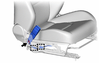
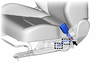
2. REMOVE FRONT SEAT INNER BELT ASSEMBLY (for Driver Side)
| (a) Disengage the claw and clamp. |
|
| (b) Disengage the clamps. |
|
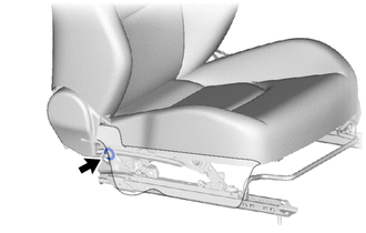
(c) Remove the nut and front seat inner belt assembly.
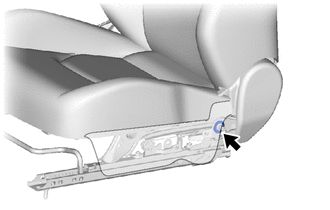
| (d) Remove the front seat belt anchor plate. |
|
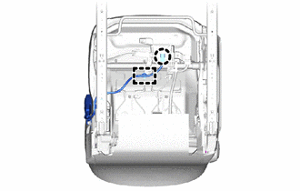
3. REMOVE FRONT SEAT INNER BELT ASSEMBLY (for Front Passenger Side)
| (a) Disconnect the rubber of the separate type front seatback cover. |
|
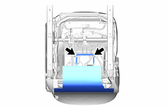
| (b) Disconnect the connector. |
|
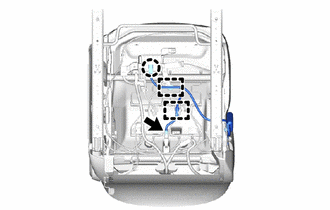
(c) Disengage the claw and clamps.
| (d) Disengage the clamps. |
|
(e) Remove the nut and front seat inner belt assembly.
| (f) Remove the front seat belt anchor plate. |
|
 Components
COMPONENTS ILLUSTRATION
*A for Driver Side *B for Front Passenger Side *1 FRONT SEAT INNER BELT ASSEMBLY *2 FRONT SEAT BELT ANCHOR PLATE *3 SEPARATE TYPE FRONT SEATBACK COVER - -
Tightening torque for "Major areas involving basic vehicle performance such as moving/turning/stopping" : N*m (kgf*cm, ft...
 Inspection
INSPECTION PROCEDURE 1. INSPECT FRONT SEAT INNER BELT ASSEMBLY (for Driver Side) (a) Check the resistance. (1) Measure the resistance according to the value(s) in the table below...
Other information:
Toyota Yaris XP210 (2020-2026) Reapir and Service Manual: Steering Lock does not Lock
DESCRIPTION The steering lock ECU (steering lock actuator or upper bracket assembly) activates the steering lock motor and moves the lock bar into the steering column to lock the steering. When the steering lock is operating, the steering may not lock when the lock bar is not aligned with the lock hole of the steering column...
Toyota Yaris XP210 (2020-2026) Reapir and Service Manual: Installation
INSTALLATION PROCEDURE 1. INSTALL REAR CONSOLE BOX ASSEMBLY (a) Engage the claws and guides to install the rear console box assembly as shown in the illustration. Install in this Direction (1) Install in this Direction (2) (b) Install the 2 bolts and 2 screws...
Categories
- Manuals Home
- Toyota Yaris Owners Manual
- Toyota Yaris Service Manual
- Immobilizer System
- Headlights
- To Set Speed
- New on site
- Most important about car
Fuel Gauge
The fuel gauge shows approximately how much fuel is remaining in the tank when the ignition is switched ON. We recommend keeping the tank over 1/4 full.
