
Toyota Yaris: Front Seat Inner Belt Assembly / Components
COMPONENTS
ILLUSTRATION
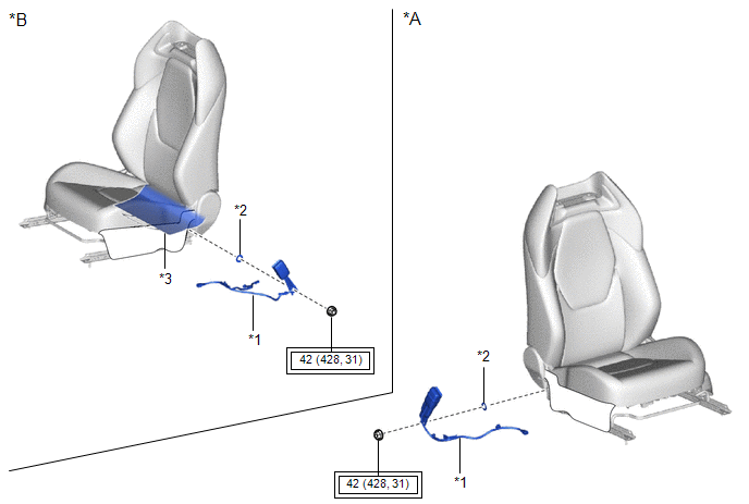
| *A | for Driver Side | *B | for Front Passenger Side |
| *1 | FRONT SEAT INNER BELT ASSEMBLY | *2 | FRONT SEAT BELT ANCHOR PLATE |
| *3 | SEPARATE TYPE FRONT SEATBACK COVER | - | - |
 | Tightening torque for "Major areas involving basic vehicle performance such as moving/turning/stopping" : N*m (kgf*cm, ft.*lbf) | - | - |

 Removal
REMOVAL CAUTION / NOTICE / HINT CAUTION: Be sure to read Precaution thoroughly before servicing.
Click here
NOTICE: If a front seat airbag assembly has been deployed, replace the front seat airbag assembly, front seatback frame sub-assembly, separate type front seatback pad, separate type front seatback cover and front seatback pad with cover with the necessary parts in accordance with the extent of the collision damage...
Other information:
Toyota Yaris XP210 (2020-2026) Reapir and Service Manual: Rear Brake Flexible Hose
ComponentsCOMPONENTS ILLUSTRATION *1 REAR FLEXIBLE HOSE *2 GASKET *3 UNION BOLT *4 BRAKE LINE Tightening torque for "Major areas involving basic vehicle performance such as moving/turning/stopping": N*m (kgf*cm, ft.*lbf) * For use with a union nut wrench ● Non-reusable part - - InstallationINSTALLATION CAUTION / NOTICE / HINT HINT: Use the same procedure for the RH side and LH side...
Toyota Yaris XP210 (2020-2026) Reapir and Service Manual: Terminals Of Ecu
TERMINALS OF ECU TERMINALS OF ECU *a Component without harness connected (Skid Control ECU [Brake Actuator Assembly]) - - Terminal No. (Symbol) Terminal Description 1 (GND2) Pump motor ground 2 - (Not used) 3 - (Not used) 4 - (Not used) 5 (STP2) Stop light switch assembly input 6 - (Not used) 7 - (Not used) 8 - (Not used) 9 - (Not used) 10 (CANL) CAN communication line L 11 - (Not used) 12 (IGR) ECU power supply input 13 (BM) Motor relay power supply 14 (SP1) Speed signal output for speedometer 15 (RR-) Rear wheel speed RH (-) signal input 16 (RR+) Rear wheel speed RH (+) power supply output 17 (FL-) Front wheel speed LH (-) signal input 18 (FL+) Front wheel speed LH (+) power supply output 19 - (Not used) 20 - (Not used) 21 - (Not used) 22 (CANH) CAN communication line H 23 - (Not used) 24 - (Not used) 25 (GND1) Skid control ECU (brake actuator assembly) ground 26 (STPO) Stop light switch assembly output 27 - (Not used) 28 (RL-) Rear wheel speed LH (-) signal input 29 (RL+) Rear wheel speed LH (+) power supply output 30 (FR-) Front wheel speed RH (-) signal input 31 (FR+) Front wheel speed RH (+) power supply output 32 - (Not used) 33 (CSW) VSC OFF switch (combination switch assembly) input 34 - (Not used) 35 (STP) Stop light switch assembly input 36 (CA2H) CAN communication line H 37 (CA2L) CAN communication line L 38 (+BS) Solenoid relay power supply TERMINAL INSPECTION (a) Disconnect the A108 connector and measure the voltage or resistance on the wire harness side...
Categories
- Manuals Home
- Toyota Yaris Owners Manual
- Toyota Yaris Service Manual
- Immobilizer System
- Power Integration No.1 System Missing Message (B235287,B235587,B235787-B235987)
- Engine & Hybrid System
- New on site
- Most important about car
Fuel-Filler Lid and Cap
WARNING
When removing the fuel-filler cap, loosen the cap slightly and wait for any hissing to stop, then remove it
Fuel spray is dangerous. Fuel can burn skin and eyes and cause illness if ingested. Fuel spray is released when there is pressure in the fuel tank and the fuel-filler cap is removed too quickly.

Copyright © 2026 www.toyaris4.com