Toyota Yaris: Active Torque Split Awd System / AWD Control Switch Circuit
DESCRIPTION
Operate the AWD control switch (No. 2 combination switch assembly) and check that the Data List display and the messages in the multi-information display change according to the switch operation.
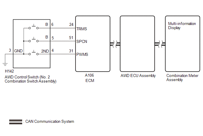
WIRING DIAGRAM
CAUTION / NOTICE / HINT
NOTICE:
Before replacing the ECM, refer to Registration.
Click here

PROCEDURE
| 1. | CHECK CAN COMMUNICATION SYSTEM |
(a) Using the GTS, check for DTCs.
Click here

(b) Check that DTCs indicating a CAN communication system malfunction are not output.
| Result | Proceed to |
|---|---|
| DTCs are not output | A |
| DTCs are output | B |
| B |
 | INSPECT CAN COMMUNICATION SYSTEM |
|

| 2. | READ VALUE USING GTS (DRIVE MODE STATUS) |
(a) According to the display on the GTS, read the Data List.
Powertrain > Engine > Data List| Tester Display | Measurement Item | Range | Normal Condition | Diagnostic Note |
|---|---|---|---|---|
| Drive Mode Status | Drive Mode Status | Normal / Power / Sport / Sport / Sport+ / Comfort / ECO / Track | - | - |
| Tester Display |
|---|
| Drive Mode Status |
(b) Operate the AWD control switch (No. 2 combination switch assembly) and check that the Data List display and the messages in the multi-information display change according to the switch operation.
OK:
| AWD Control Switch (No. 2 Combination Switch Assembly) Operation | Data List Display | Multi-information Display Message |
|---|---|---|
| PUSH NORMAL | Normal | NORMAL |
| SPORT | Sport | SPORT |
| TRACK | Track | TRACK |
| Result | Proceed to |
|---|---|
| When the switch is operated, the Data List display and message do not change | A |
| When the switch is operated, the Data List display changes, but the message does not change | B |
| When the switch is operated, the Data List display and indicator change normally | C |
| B |
 | GO TO METER / GAUGE SYSTEM (HOW TO PROCEED WITH TROUBLESHOOTING) |
| C |
 | CHECK INTERMITTENT PROBLEMS |
|

| 3. | INSPECT NO. 2 COMBINATION SWITCH ASSEMBLY |
Click here

| NG |
 | REPLACE NO. 2 COMBINATION SWITCH ASSEMBLY |
|

| 4. | CHECK HARNESS AND CONNECTOR (ECM - NO. 2 COMBINATION SWITCH ASSEMBLY) |
(a) Turn the ignition switch off.
(b) Disconnect the A106 ECM connector.
(c) Disconnect the H142 AWD control switch (No. 2 combination switch assembly) connector.
(d) Measure the resistance according to the value(s) in the table below.
Standard Resistance:
| Tester Connection | Condition | Specified Condition |
|---|---|---|
| A106-24 (TRMS) - H142-6 (B) | Always | Below 1 Ω |
| A106-31 (PWMS) - H142-4 (2ND) | Always | Below 1 Ω |
| A106-51 (SPCN) - H142-5 (B) | Always | Below 1 Ω |
| H142-3 (GND) - Body ground | Always | Below 1 Ω |
| A106-24 (TRMS) or H142-6 (B) - Body ground | Always | 10 kΩ or higher |
| A106-31 (PWMS) or H142-4 (2ND) - Body ground | Always | 10 kΩ or higher |
| A106-24 (TRMS) or H142-6 (B) - A106-31 (PWMS) or H142-4 (2ND) | Always | 10 kΩ or higher |
| OK |
 | REPLACE ECM |
| NG |
 | REPAIR OR REPLACE HARNESS OR CONNECTOR |
 AWD Warning Light does not Come ON
DESCRIPTION Refer to "AWD Warning Light Remains ON". Click here
WIRING DIAGRAM Refer to "AWD Warning Light Remains ON". Click here
CAUTION / NOTICE / HINT Refer to "AWD Warning Light Remains ON"...

Other information:
Toyota Yaris XP210 (2020-2026) Reapir and Service Manual: Charge Air Cooler Temperature Sensor Bank 1 Circuit Short to Ground (P007A11)
DESCRIPTION The intake air temperature sensor, built into the No. 2 turbo pressure sensor, monitors the intake air temperature. The intake air temperature sensor has a built-in thermistor with a resistance that varies according to the temperature of the intake air...
Toyota Yaris XP210 (2020-2026) Reapir and Service Manual: Terminals Of Ecu
TERMINALS OF ECU CHECK ECM HINT: The standard voltage, resistance and waveform between each pair of the ECM terminals is shown in the table below. The appropriate conditions for checking each pair of the terminals are also indicated. The result of checks should be compared with the standard voltage, resistance and waveform for each pair of the terminals as displayed in the Specified Condition column...
Categories
- Manuals Home
- Toyota Yaris Owners Manual
- Toyota Yaris Service Manual
- G16e-gts (engine Mechanical)
- Adjustment
- Power Integration No.1 System Missing Message (B235287,B235587,B235787-B235987)
- New on site
- Most important about car
Liftgate/Trunk Lid
WARNING
Never allow a person to ride in the luggage compartment/trunk
Allowing a person to ride in the luggage compartment/trunk is dangerous. The person in the luggage compartment/trunk could be seriously injured or killed during sudden braking or a collision.
Do not drive with the liftgate/trunk lid open