Toyota Yaris: Front Seat Inner Belt Assembly / Installation
INSTALLATION
CAUTION / NOTICE / HINT
HINT:
- Use the same procedure for the driver side and front passenger side.
- The procedure listed below is for the driver side.
PROCEDURE
1. INSTALL FRONT SEAT INNER BELT ASSEMBLY (for Driver Side)
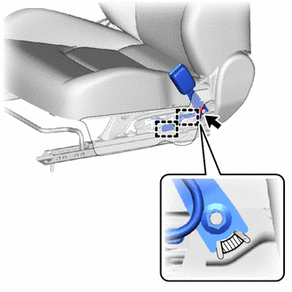
| (a) Install the front seat belt anchor plate. |
|
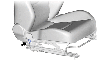
(b) Install the front seat inner belt assembly with the nut.
Torque:
42 N·m {428 kgf·cm, 31 ft·lbf}
NOTICE:
Do not allow the anchor part of the front seat inner belt assembly to overlap the protruding part of the separate type front seat cushion spring assembly.
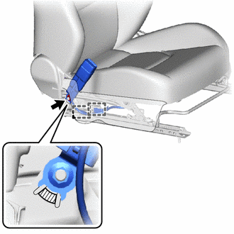
 | Protruding Part |
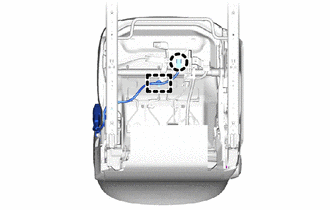
(c) Engage the clamps.
| (d) Engage the clamp and claw. |
|
2. INSTALL FRONT SEAT INNER BELT ASSEMBLY (for Front Passenger Side)
| (a) Install the front seat belt anchor plate. |
|
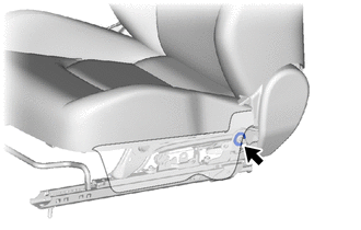
(b) Install the front seat inner belt assembly with the nut.
 | Protruding Part |
Torque:
42 N·m {428 kgf·cm, 31 ft·lbf}
NOTICE:
Do not allow the anchor part of the front seat inner belt assembly to overlap the protruding part of the separate type front seat cushion spring assembly.
(c) Engage the clamps.
| (d) Engage the clamps and claw. |
|
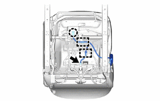
(e) Connect the connector.
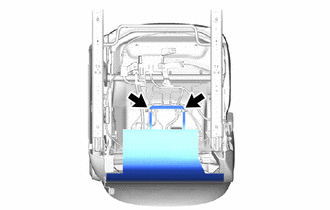
| (f) Connect the rubber of the separate type front seatback cover. |
|
3. INSTALL FRONT SEAT ASSEMBLY
Click here

 Inspection
INSPECTION PROCEDURE 1. INSPECT FRONT SEAT INNER BELT ASSEMBLY (for Driver Side) (a) Check the resistance. (1) Measure the resistance according to the value(s) in the table below...

Other information:
Toyota Yaris XP210 (2020-2026) Reapir and Service Manual: Diagnostic Trouble Code Chart
D..
Toyota Yaris XP210 (2020-2026) Reapir and Service Manual: Replacement
REPLACEMENT CAUTION / NOTICE / HINT The necessary procedures (adjustment, calibration, initialization, or registration) that must be performed after parts are removed and installed, or replaced during the transaxle case oil seal and front dirve shaft oil seal RH removal/installation are shown below...
Categories
- Manuals Home
- Toyota Yaris Owners Manual
- Toyota Yaris Service Manual
- Opening and Closing the Liftgate/Trunk Lid
- Key Battery Replacement
- Adjustment
- New on site
- Most important about car
Supplemental Restraint System (SRS) Precautions
The front and side supplemental restraint systems (SRS) include different types of air bags. Please verify the different types of air bags which are equipped on your vehicle by locating the “SRS AIRBAG” location indicators. These indicators are visible in the area where the air bags are installed.
The air bags are installed in the following locations:
The steering wheel hub (driver air bag) The front passenger dashboard (front passenger air bag) The outboard sides of the front seatbacks (side air bags) The front and rear window pillars, and the roof edge along both sides (curtain air bags)