Toyota Yaris: Propeller Shaft Assembly / Inspection
INSPECTION
PROCEDURE
1. INSPECT PROPELLER SHAFT WITH CENTER BEARING ASSEMBLY
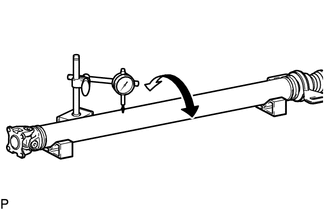
| (a) Using a dial indicator, measure the propeller shaft runout for the front side. Maximum Runout: 0.4 mm (0.0157 in.) If the runout is more than the maximum, replace the propeller shaft with center bearing assembly. NOTICE: Place the dial indicator on the center of the shaft, and perpendicular to the shaft. |
|
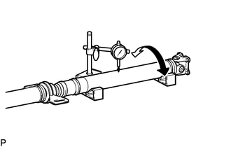
| (b) Using a dial indicator, measure the propeller shaft runout for the rear side. Maximum Runout: 0.4 mm (0.0157 in.) If the runout is more than the maximum, replace the propeller shaft with center bearing assembly. NOTICE: Place the dial indicator on the center of the shaft, and perpendicular to the shaft. |
|
 Removal
REMOVAL CAUTION / NOTICE / HINT The necessary procedures (adjustment, calibration, initialization, or registration) that must be performed after parts are removed and installed, or replaced during the propeller shaft with center bearing assembly removal/installation are shown below...
 Installation
INSTALLATION PROCEDURE 1. TEMPORARILY INSTALL PROPELLER SHAFT WITH CENTER BEARING ASSEMBLY (a) Completely remove any oil or the like and clean the contact surfaces of the transfer assembly and propeller shaft with center bearing assembly...
Other information:
Toyota Yaris XP210 (2020-2026) Reapir and Service Manual: Inspection
INSPECTION PROCEDURE 1. INSPECT FRONT NO. 1 DIFFERENTIAL CASE SUB-ASSEMBLY (a) Using SST, rotate the front differential side gear as shown in the illustration. SST: 09528-52010 09528-05030 Standard: The front differential side gear does not lock when rotated in either direction...
Toyota Yaris XP210 (2020-2026) Reapir and Service Manual: Camshaft Position "B" - Actuator Bank 1 Circuit Open (P001313)
DESCRIPTION The Variable Valve Timing (VVT) system adjusts the exhaust valve timing to improve driveability. The engine oil pressure turns the VVT controller (camshaft timing exhaust gear assembly) to adjust the valve timing. The cam timing oil control solenoid assembly (for exhaust camshaft) operates according to signals received from the ECM to control the position of the camshaft timing oil control valve assembly (exhaust camshaft timing gear bolt assembly) and supply engine oil...
Categories
- Manuals Home
- Toyota Yaris Owners Manual
- Toyota Yaris Service Manual
- Key Battery Replacement
- Diagnostic Trouble Code Chart
- Immobilizer System
- New on site
- Most important about car
Supplemental Restraint System (SRS) Precautions
The front and side supplemental restraint systems (SRS) include different types of air bags. Please verify the different types of air bags which are equipped on your vehicle by locating the “SRS AIRBAG” location indicators. These indicators are visible in the area where the air bags are installed.
The air bags are installed in the following locations:
The steering wheel hub (driver air bag) The front passenger dashboard (front passenger air bag) The outboard sides of the front seatbacks (side air bags) The front and rear window pillars, and the roof edge along both sides (curtain air bags)