Toyota Yaris: Propeller Shaft Assembly / Removal
REMOVAL
CAUTION / NOTICE / HINT
The necessary procedures (adjustment, calibration, initialization, or registration) that must be performed after parts are removed and installed, or replaced during the propeller shaft with center bearing assembly removal/installation are shown below.
Necessary Procedures After Parts Removed/Installed/Replaced| Replaced Part or Performed Procedure | Necessary Procedure | Effect/Inoperative Function when Necessary Procedure not Performed | Link |
|---|---|---|---|
| Gas leak from exhaust system is repaired | Inspection After Repair |
|
|

PROCEDURE
1. REMOVE FRONT EXHAUST PIPE ASSEMBLY
Click here

2. REMOVE FRONT FLOOR COVER LH
| (a) Remove the bolt and 3 clips. |
|
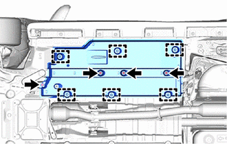
(b) Disengage the 6 clamps to remove the front floor cover LH from the vehicle body.
3. REMOVE FRONT FLOOR COVER RH
HINT:
Use the same procedure as for the LH side.
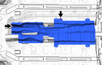
4. REMOVE FRONT NO. 1 FLOOR HEAT INSULATOR SUB-ASSEMBLY
| (a) Remove the 2 nuts and front No. 1 floor heat insulator sub-assembly from the vehicle body. |
|
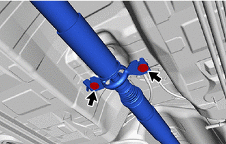
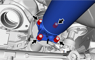
5. REMOVE PROPELLER SHAFT WITH CENTER BEARING ASSEMBLY
| (a) Remove the 2 bolts and 2 center No. 2 support bearing washers, and separate the center support bearing. |
|
| (b) Place matchmarks on the rear differential carrier assembly and propeller shaft with center bearing assembly. |
|
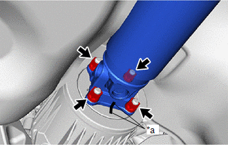
(c) Remove the 4 nuts and 4 washers, and separate the propeller shaft with center bearing assembly from the rear differential carrier assembly.
| (d) Place matchmarks on the transfer assembly and propeller shaft with center bearing assembly. |
|
(e) Remove the 4 nuts and 4 washers, and separate the propeller shaft with center bearing assembly from the transfer assembly.
 Components
COMPONENTS ILLUSTRATION
*1 FRONT FLOOR COVER LH *2 FRONT FLOOR COVER RH *3 FRONT NO. 1 FLOOR HEAT INSULATOR SUB-ASSEMBLY - -
N*m (kgf*cm, ft...
 Inspection
INSPECTION PROCEDURE 1. INSPECT PROPELLER SHAFT WITH CENTER BEARING ASSEMBLY (a) Using a dial indicator, measure the propeller shaft runout for the front side...
Other information:
Toyota Yaris XP210 (2020-2026) Reapir and Service Manual: Control Module Internal Temperature Sensor A/B Correlation Signal Compare Failure (C100A62,C1A9304,C1A9308,C1A9444,C1A9445,C1A9447,C1A9487-C1A961C)
DESCRIPTION When an internal malfunction is detected in the forward recognition camera, these DTCs are stored. DTC No. Detection Item DTC Detection Condition Trouble Area C100A62 Control Module Internal Temperature Sensor A/B Correlation Signal Compare Failure A forward recognition camera internal malfunction is detected...
Toyota Yaris XP210 (2020-2026) Reapir and Service Manual: System Description
SYSTEM DESCRIPTION POWER MIRROR CONTROL SYSTEM DESCRIPTION (a) This system has the following functions: electrical remote control mirror function, power retract mirror function, auto power retract mirror function and mirror heater function. FUNCTION OF MAIN COMPONENT Component Function Outer rear view mirror assembly Vertical mirror motor Receives signals from the outer mirror switch assembly and adjusts the mirror surface position vertically...
Categories
- Manuals Home
- Toyota Yaris Owners Manual
- Toyota Yaris Service Manual
- Fuse Panel Description
- Fuel Gauge
- How to connect USB port/Auxiliary jack
- New on site
- Most important about car
Break-In Period
No special break-in is necessary, but a few precautions in the first 600 miles (1,000 km) may add to the performance, economy, and life of the vehicle.
Do not race the engine. Do not maintain one constant speed, either slow or fast, for a long period of time. Do not drive constantly at full-throttle or high engine rpm for extended periods of time. Avoid unnecessary hard stops. Avoid full-throttle starts.