Toyota Yaris: Propeller Shaft Assembly / Components
COMPONENTS
ILLUSTRATION
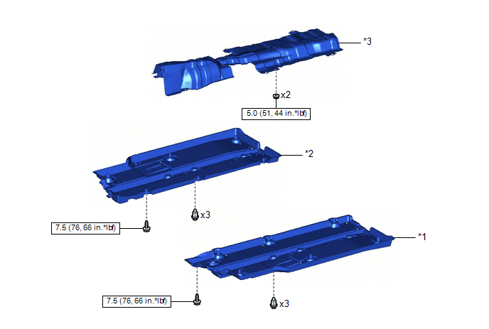
| *1 | FRONT FLOOR COVER LH | *2 | FRONT FLOOR COVER RH |
| *3 | FRONT NO. 1 FLOOR HEAT INSULATOR SUB-ASSEMBLY | - | - |
 | N*m (kgf*cm, ft.*lbf): Specified torque | - | - |
ILLUSTRATION
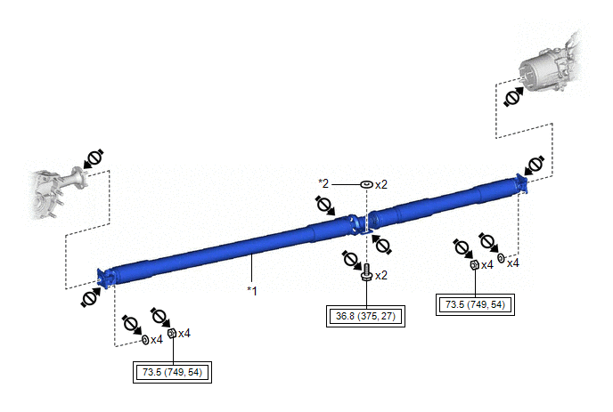
| *1 | PROPELLER SHAFT WITH CENTER BEARING ASSEMBLY | *2 | CENTER NO. 2 SUPPORT BEARING WASHER |
 | Tightening torque for "Major areas involving basic vehicle performance such as moving/turning/stopping": N*m (kgf*cm, ft.*lbf) |
 | Do not apply lubricants |

 Removal
REMOVAL CAUTION / NOTICE / HINT The necessary procedures (adjustment, calibration, initialization, or registration) that must be performed after parts are removed and installed, or replaced during the propeller shaft with center bearing assembly removal/installation are shown below...
Other information:
Toyota Yaris XP210 (2020-2026) Reapir and Service Manual: Parts Location
PARTS LOCATION ILLUSTRATION *1 BRAKE ACTUATOR ASSEMBLY - SKID CONTROL ECU *2 ECM *3 TEMPERATURE SENSOR *4 AWD LINEAR SOLENOID (TRANSMISSION COUPLING ASSEMBLY) *5 AWD ECU ASSEMBLY - - ILLUSTRATION *1 COMBINATION METER ASSEMBLY - AWD WARNING (MULTI-INFORMATION DISPLAY) *2 AWD CONTROL SWITCH (NO...
Toyota Yaris XP210 (2020-2026) Reapir and Service Manual: Room Temperature Sensor Circuit Short to Battery or Open (B141A15)
DESCRIPTION The cooler thermistor (room temperature sensor) is installed in the instrument panel to detect the cabin temperature, which is used to control the air conditioning system. The resistance of the cooler thermistor (room temperature sensor) changes in accordance with the cabin temperature...
Categories
- Manuals Home
- Toyota Yaris Owners Manual
- Toyota Yaris Service Manual
- Opening and Closing the Liftgate/Trunk Lid
- Maintenance
- Fuel Gauge
- New on site
- Most important about car
Fuel Gauge
The fuel gauge shows approximately how much fuel is remaining in the tank when the ignition is switched ON. We recommend keeping the tank over 1/4 full.

Copyright © 2026 www.toyaris4.com