Toyota Yaris: Sfi System / Actuator Supply Voltage "A" Circuit Short to Ground or Open (P065714)
DESCRIPTION
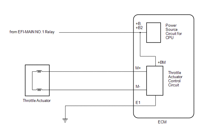
The electronic throttle control system has a dedicated power supply circuit. The voltage (+BM, +BM2) is monitored and when it is low (less than 4 V), the ECM determines that there is a malfunction in the electronic throttle control system and cuts off the current to the throttle actuator.
When the voltage becomes unstable, the electronic throttle control system itself becomes unstable. For this reason, when the voltage is low, the current to the throttle actuator is cut. If repairs are made and the system returns to normal, turn the ignition switch off. If a malfunction is not detected, the ECM allows current to flow to the throttle actuator so that it can operate.

| DTC No. | Detection Item | DTC Detection Condition | Trouble Area | MIL | Note |
|---|---|---|---|---|---|
| P065714 | Actuator Supply Voltage "A" Circuit Short to Ground or Open | An open or short is detected in the electronic throttle control system power source (+BM) circuit (1 trip detection logic). |
| Comes on | SAE: P0658 |
MONITOR DESCRIPTION
The ECM monitors the auxiliary battery supply voltage applied to the throttle actuator.
When the power supply voltage (+BM, +BM2) is less than 4 V for 0.8 seconds or more, the ECM interprets this as an open or ground short in the power supply circuit, then illuminates the MIL and stores a DTC.
MONITOR STRATEGY
| Required Sensors/Components | Throttle actuator Throttle valve (throttle body with motor assembly) |
| Frequency of Operation | Continuous |
CONFIRMATION DRIVING PATTERN

- Connect the GTS to the DLC3.
- Turn the ignition switch to ON.
- Turn the GTS on.
- Clear the DTCs (even if no DTCs are stored, perform the clear DTC procedure).
- Turn the ignition switch off and wait for at least 30 seconds.
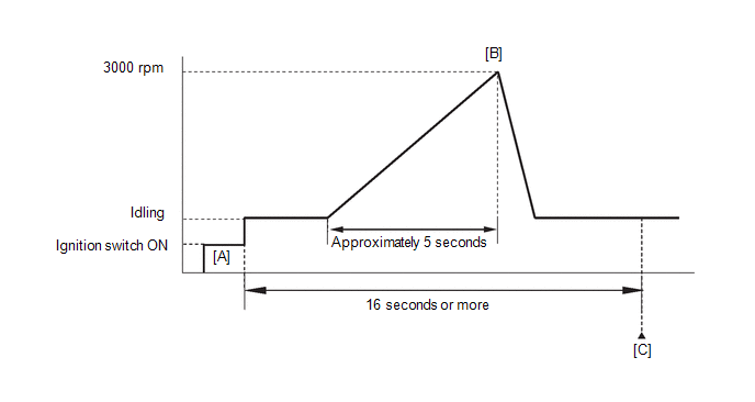
- Turn the ignition switch to ON [A].
- Turn the GTS on.
- Start the engine.
- Slowly depress the accelerator pedal, raise the engine speed to approximately 3000 rpm over approximately 5 seconds, and then idle the engine [B].
- Check that 16 seconds or more have elapsed since the engine was started.
- Enter the following menus: Powertrain / Engine / Trouble Codes [C].
-
Read the pending DTCs.
HINT:
- If a pending DTC is output, the system is malfunctioning.
- If a pending DTC is not output, perform the following procedure.
- Enter the following menus: Powertrain / Engine / Utility / All Readiness.
- Input the DTC: P065714.
-
Check the DTC judgment result.
GTS Display
Description
NORMAL
- DTC judgment completed
- System normal
ABNORMAL
- DTC judgment completed
- System abnormal
INCOMPLETE
- DTC judgment not completed
- Perform driving pattern after confirming DTC enabling conditions
HINT:
- If the judgment result is NORMAL, the system is normal.
- If the judgment result is ABNORMAL, the system is malfunctioning.
- If the judgment result is INCOMPLETE, perform steps [B] through [C] again.
FAIL-SAFE
When any of these DTCs or other DTCs relating to Electronic Throttle Control System (ETCS) malfunctions are stored, the ECM enters fail-safe mode. During fail-safe mode, the ECM cuts the current to the throttle actuator, and the throttle valve is returned to a 8° throttle valve opening angle by the return spring. The ECM then adjusts the engine output by controlling the fuel injection (intermittent fuel-cut) and ignition timing, in accordance with the accelerator pedal angle, to allow the vehicle to continue running at a minimal speed. If the accelerator pedal is depressed firmly and gently, the vehicle can be driven slowly.
Fail-safe mode continues until a pass condition is detected, and the switch is turned off.
WIRING DIAGRAM
Refer to DTC P210018.
Click here

CAUTION / NOTICE / HINT
NOTICE:
Inspect the fuses for circuits related to this system before performing the following procedure.
HINT:
Read Freeze Frame Data using the GTS. The ECM records vehicle and driving condition information as Freeze Frame Data the moment a DTC is stored. When troubleshooting, Freeze Frame Data can help determine if the vehicle was moving or stationary, if the engine was warmed up or not, if the air fuel ratio was lean or rich, and other data from the time the malfunction occurred.
PROCEDURE
| 1. | CHECK DTC OUTPUT |
(a) Read the DTCs.
Powertrain > Engine > Trouble Codes| Result | Proceed to |
|---|---|
| P065714 is output | A |
| DTC is not output | B |
| A |
 | REPLACE ECM |
| B |
 | CHECK FOR INTERMITTENT PROBLEMS |
 Fuel Pump Control Module Internal Electronic Failure (P064A49)
MONITOR DESCRIPTION The fuel pump control ECU has a self-diagnosis function. If there is an internal malfunction, the fuel pump control ECU sends a malfunction signal to the ECM via the FPC drive circuit...
 Actuator Supply Voltage "A" Stuck On (P06579E)
MONITOR DESCRIPTION The ECM monitors the output voltage to the throttle actuator. This self-check ensures that the ECM is functioning properly. The output voltage is usually 0 V when the ignition switch is turned off...
Other information:
Toyota Yaris XP210 (2020-2025) Reapir and Service Manual: G16e-gts Air Cleaner Filter Element
ComponentsCOMPONENTS ILLUSTRATION *1 AIR CLEANER CAP SUB-ASSEMBLY *2 AIR CLEANER FILTER ELEMENT SUB-ASSEMBLY RemovalREMOVAL PROCEDURE 1. SEPARATE AIR CLEANER CAP SUB-ASSEMBLY (a) Disconnect the 2 clamp hooks from the air cleaner cap sub-assembly...
Toyota Yaris XP210 (2020-2025) Reapir and Service Manual: Power Window Switch Malfunction (B2312)
DESCRIPTION The power window regulator motor assemblies are operated by the multiplex network master switch assembly or power window regulator switch assembly. The power window regulator motor assemblies have motor, regulator and ECU functions. This DTC is stored when the ECU built into a power window regulator motor assembly and multiplex network master switch assembly determine that the multiplex network master switch assembly or power window regulator switch assembly is stuck...
Categories
- Manuals Home
- Toyota Yaris Owners Manual
- Toyota Yaris Service Manual
- Engine Start Function When Key Battery is Dead
- Brake System Control Module "A" System Voltage System Voltage Low (C137BA2)
- Auto Lock/Unlock Function
- New on site
- Most important about car
Refueling
Before refueling, close all the doors, windows, and the liftgate/trunk lid, and switch the ignition OFF.
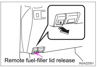
To open the fuel-filler lid, pull the remote fuel-filler lid release.

