Toyota Yaris: Power Window Control System / Power Window Switch Malfunction (B2312)
DESCRIPTION
The power window regulator motor assemblies are operated by the multiplex network master switch assembly or power window regulator switch assembly. The power window regulator motor assemblies have motor, regulator and ECU functions.
This DTC is stored when the ECU built into a power window regulator motor assembly and multiplex network master switch assembly determine that the multiplex network master switch assembly or power window regulator switch assembly is stuck.
Master Switch| DTC No. | Detection Item | DTC Detection Condition | Trouble Area | DTC Output from |
|---|---|---|---|---|
| B2312 | Power Window Switch Malfunction |
| Multiplex network master switch assembly | Master Switch |
| DTC No. | Detection Item | DTC Detection Condition | Trouble Area | DTC Output from |
|---|---|---|---|---|
| B2312 | Power Window Switch Malfunction |
|
| D-Door Motor |
| DTC No. | Detection Item | DTC Detection Condition | Trouble Area | DTC Output from |
|---|---|---|---|---|
| B2312 | Power Window Switch Malfunction |
|
| P-Door Motor |
WIRING DIAGRAM
Refer to DTC B2311.
Click here
.gif)
CAUTION / NOTICE / HINT
NOTICE:
- DTC B2312 is stored in the multiplex network master switch assembly and in each power window regulator motor assembly.
-
If a power window regulator motor assembly has been replaced with a new one, initialize the power window control system.
Click here
- Inspect the fuses for circuits related to this system before performing the following procedure.
-
The power window control system uses the LIN communication system. Inspect the communication function by following How to Proceed with Troubleshooting. Troubleshoot the power window control system after confirming that the communication system is functioning properly.
Click here
HINT:
If DTC B2312 is not output again after the DTC has been cleared, the DTC was stored due to the switch being held in the same position continuously.
PROCEDURE
| 1. | CHECK FOR DTC |
(a) Check for DTCs.
Body Electrical > Master Switch > Trouble Codes Body Electrical > D-Door Motor > Trouble Codes Body Electrical > P-Door Motor > Trouble Codes| Result | Proceed to |
|---|---|
| Any Master Switch DTCs in the table below are output | A |
| Any D-Door Motor DTCs in the table below are output | B |
| Any P-Door Motor DTCs in the table below are output | C |
| No DTCs in the table below are output | D |
| Malfunction Status | System | Related DTCs | |
|---|---|---|---|
| Power Window Switch Malfunction | Master Switch | B2312 | ON Switch Failure |
| D-Door Motor | B2312 | Master Switch of Driver side door Malfunction | |
| P-Door Motor | B2312 | Power Window Switch of Passenger side door Malfunction | |
| A |
.gif) | REPLACE MULTIPLEX NETWORK MASTER SWITCH ASSEMBLY |
| C |
| GO TO STEP 5 |
| D |
| END (DTC WAS STORED DUE TO SWITCH BEING OPERATED FOR 20 SECONDS OR MORE) |
|
.gif)
| 2. | READ VALUE USING GTS (D-DOOR MOTOR) |
(a) Read the Data List according to the display on the GTS.
Body Electrical > D-Door Motor > Data List| Tester Display | Measurement Item | Range | Normal Condition | Diagnostic Note |
|---|---|---|---|---|
| D Door P/W Up SW | Driver door power window manual up switch signal | OFF or ON | OFF: Driver door power window manual up switch not being operated ON: Driver door power window manual up switch being operated | - |
| D Door P/W Down SW | Driver door power window manual down switch signal | OFF or ON | OFF: Driver door power window manual down switch not being operated ON: Driver door power window manual down switch being operated | - |
| Tester Display |
|---|
| D Door P/W Up SW |
| D Door P/W Down SW |
OK:
On the GTS screen, ON or OFF is displayed accordingly.
| OK |
| REPLACE POWER WINDOW REGULATOR MOTOR ASSEMBLY (for Driver Door) |
|
| 3. | CHECK MULTIPLEX NETWORK MASTER SWITCH ASSEMBLY |
(a) Disconnect the power window regulator motor assembly (for driver door) connector.
| (b) Measure the voltage according to the value(s) in the table below. Standard Voltage:
|
|
| OK |
| REPLACE POWER WINDOW REGULATOR MOTOR ASSEMBLY (for Driver Door) |
|
| 4. | CHECK HARNESS AND CONNECTOR (MULTIPLEX NETWORK MASTER SWITCH ASSEMBLY - POWER WINDOW REGULATOR MOTOR ASSEMBLY (for Driver Door)) |
(a) Disconnect the L13 multiplex network master switch assembly connector.
(b) Measure the resistance according to the value(s) in the table below.
Standard Resistance:
| Tester Connection | Condition | Specified Condition |
|---|---|---|
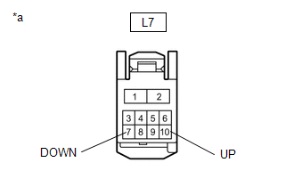
| L13-20 (UP) or L7-10 (UP) - Body ground | Always | 10 kΩ or higher |
| L13-15 (DOWN) or L7-7 (DOWN) - Body ground | Always | 10 kΩ or higher |
| OK |
| REPLACE MULTIPLEX NETWORK MASTER SWITCH ASSEMBLY |
| NG |
| REPAIR OR REPLACE HARNESS OR CONNECTOR |
| 5. | READ VALUE USING GTS (P-DOOR MOTOR) |
(a) Read the Data List according to the display on the GTS.
Body Electrical > P-Door Motor > Data List| Tester Display | Measurement Item | Range | Normal Condition | Diagnostic Note |
|---|---|---|---|---|
| P Door P/W Auto SW | Front passenger door power window auto switch signal | OFF or ON | OFF: Front passenger door power window auto up or auto down switch not being operated ON: Front passenger door power window auto up or auto down switch being operated | - |
| P Door P/W Up SW | Front passenger door power window manual up switch signal | OFF or ON | OFF: Front passenger door power window manual up switch not being operated ON: Front passenger door power window manual up switch being operated | - |
| P Door P/W Down SW | Front passenger door power window manual down switch signal | OFF or ON | OFF: Front passenger door power window manual down switch not being operated ON: Front passenger door power window manual down switch being operated | - |
| Tester Display |
|---|
| P Door P/W Auto SW |
| P Door P/W Up SW |
| P Door P/W Down SW |
OK:
On the GTS screen, ON or OFF is displayed accordingly.
| OK |
| REPLACE POWER WINDOW REGULATOR MOTOR ASSEMBLY (for Front Passenger Door) |
|
| 6. | INSPECT POWER WINDOW REGULATOR SWITCH ASSEMBLY |
Click here
| NG |
| REPLACE POWER WINDOW REGULATOR SWITCH ASSEMBLY |
|
| 7. | CHECK HARNESS AND CONNECTOR (POWER WINDOW REGULATOR SWITCH ASSEMBLY - POWER WINDOW REGULATOR MOTOR ASSEMBLY (for Front Passenger Door)) |
(a) Disconnect the K7 power window regulator motor assembly (for Front Passenger Door) connector.
(b) Measure the resistance according to the value(s) in the table below.
Standard Resistance:
| Tester Connection | Condition | Specified Condition |
|---|---|---|
| K13-5 (UP) or K7-10 (UP) - Body ground | Always | 10 kΩ or higher |
| K13-8 (AUTO) or K7-4 (AUTO) - Body ground | Always | 10 kΩ or higher |
| K13-4 (DOWN) or K7-7 (DOWN) - Body ground | Always | 10 kΩ or higher |
| OK |
| REPLACE POWER WINDOW REGULATOR MOTOR ASSEMBLY (for Front Passenger Door) |
| NG |
| REPAIR OR REPLACE HARNESS OR CONNECTOR |
 Power Window Motor Malfunction (B2311)
DESCRIPTION The power window regulator motor assemblies are operated by the multiplex network master switch assembly or power window regulator switch assembly...
 Glass Position Initialization Incomplete (B2313)
DESCRIPTION The power window regulator motor assemblies are operated by the multiplex network master switch assembly or power window regulator switch assembly...
Other information:
Toyota Yaris XP210 (2020-2026) Reapir and Service Manual: Throttle Actuator "A" Control System Actuator Stuck Open (P211172,P211173)
DESCRIPTION The throttle actuator is operated by the ECM, and opens and closes the throttle valve using gears. The opening angle of the throttle valve is detected by the throttle position sensor, which is mounted on the throttle body with motor assembly...
Toyota Yaris XP210 (2020-2026) Reapir and Service Manual: Components
C..
Categories
- Manuals Home
- Toyota Yaris Owners Manual
- Toyota Yaris Service Manual
- Power Integration No.1 System Missing Message (B235287,B235587,B235787-B235987)
- Fuse Panel Description
- Fuel Gauge
- New on site
- Most important about car
Key Suspend Function
If a key is left in the vehicle, the functions of the key left in the vehicle are temporarily suspended to prevent theft of the vehicle.
To restore the functions, press the unlock button on the functions-suspended key in the vehicle.