Toyota Yaris: Power Window Control System / Power Window Motor Malfunction (B2311)
DESCRIPTION
The power window regulator motor assemblies are operated by the multiplex network master switch assembly or power window regulator switch assembly. The power window regulator motor assemblies have motor, regulator and ECU functions.
This DTC is stored when a power window regulator motor assembly is malfunctioning, or the ECU built into the power window regulator motor assembly determines that the fully closed power window position has deviated approximately 20 mm (0.787 in.) or more from the normal position.
D-Door Motor| DTC No. | Detection Item | DTC Detection Condition | Trouble Area | DTC Output from |
|---|---|---|---|---|
| B2311 | Power Window Motor Malfunction | Either condition is met:
|
| D-Door Motor |
| DTC No. | Detection Item | DTC Detection Condition | Trouble Area | DTC Output from |
|---|---|---|---|---|
| B2311 | Power Window Motor Malfunction | Either condition is met:
|
| P-Door Motor |
WIRING DIAGRAM

CAUTION / NOTICE / HINT
NOTICE:
- DTC B2311 is stored in each power window regulator motor assembly.
-
If a power window regulator motor assembly has been replaced with a new one, initialize the power window control system.
Click here

-
If a power window regulator motor assembly and door window regulator sub-assembly have been removed and installed, or if a power window regulator motor assembly was reused when a door glass or door glass run was replaced, initialize the power window control system.
Click here
- Inspect the fuses for circuits related to this system before performing the following procedure.
-
The power window control system uses the LIN communication system. Inspect the communication function by following How to Proceed with Troubleshooting. Troubleshoot the power window control system after confirming that the communication system is functioning properly.
Click here
PROCEDURE
| 1. | CHECK FOR DTC |
(a) Check for DTCs.
Body Electrical > D-Door Motor > Trouble Codes Body Electrical > P-Door Motor > Trouble CodesOK:
DTC B2311 is not output.
| Result | Proceed to |
|---|---|
| Any D-Door Motor DTCs in the table below are output | A |
| Any P-Door Motor DTCs in the table below are output | B |
| No DTCs in the table below are output | C |
| Malfunction Status | System | Related DTCs | |
|---|---|---|---|
| Power Window Motor Malfunction | D-Door Motor | B2311 | Motor Malfunction |
| P-Door Motor | B2311 | Motor Malfunction | |
| B |
 | GO TO STEP 3 |
| C |
| USE SIMULATION METHOD TO CHECK |
|

| 2. | CHECK HARNESS AND CONNECTOR (POWER WINDOW REGULATOR MOTOR ASSEMBLY (for Driver Door) - AUXILIARY BATTERY AND BODY GROUND) |
| (a) Measure the voltage according to the value(s) in the table below. Standard Voltage:
|
|

(b) Measure the resistance according to the value(s) in the table below.
Standard Resistance:
| Tester Connection | Condition | Specified Condition |
|---|---|---|
| L7-1 (GND) - Body ground | Always | Below 1 Ω |
| OK |
| GO TO STEP 4 |
| NG |
| REPAIR OR REPLACE HARNESS OR CONNECTOR |
| 3. | CHECK HARNESS AND CONNECTOR (POWER WINDOW REGULATOR MOTOR ASSEMBLY (for Front Passenger Door) - AUXILIARY BATTERY AND BODY GROUND) |
| (a) Measure the voltage according to the value(s) in the table below. Standard Voltage:
|
|

(b) Measure the resistance according to the value(s) in the table below.
Standard Resistance:
| Tester Connection | Condition | Specified Condition |
|---|---|---|
| K7-1 (GND) - Body ground | Always | Below 1 Ω |
| NG |
| REPAIR OR REPLACE HARNESS OR CONNECTOR |
|
| 4. | PERFORM ACTIVE TEST USING GTS (APPLICABLE LOCATION) |
(a) Perform the Active Test according to the display on the GTS.
CAUTION:
Be careful to avoid injuries as this test causes vehicle parts to move. During the Active Test, the jam protection function will not operate.
Body Electrical > D-Door Motor > Active Test| Tester Display | Measurement Item | Control Range | Diagnostic Note |
|---|---|---|---|
| Power Window | Power window | OFF / DOWN / UP | - |
| Tester Display | Measurement Item | Control Range | Diagnostic Note |
|---|---|---|---|
| Power Window | Power window | OFF / DOWN / UP | - |
| Tester Display |
|---|
| Power Window |
| Tester Display |
|---|
| Power Window |
OK:
Each power window operates normally.
| Result | Proceed to |
|---|---|
| OK | A |
| NG (Driver door power window) | B |
| NG (Front passenger door power window) | C |
| B |
| REPLACE POWER WINDOW REGULATOR MOTOR ASSEMBLY (for Driver Door) |
| C |
| REPLACE POWER WINDOW REGULATOR MOTOR ASSEMBLY (for Front Passenger Door) |
|
| 5. | PERFORM INITIALIZATION (APPLICABLE LOCATION) |
(a) Initialize the power window regulator motor assembly.
HINT:
Initialize the power window regulator motor assembly that has DTC B2311 stored in its ECU.
Click here
|
| 6. | CHECK POWER WINDOW CONTROL SYSTEM (APPLICABLE LOCATION) |
(a) Check that the power window operates normally by opening and closing it.
HINT:
Check the power window operation of the window where DTC B2311 has been stored.
Click here
OK:
Each power window operates normally.
| Result | Proceed to |
|---|---|
| OK | A |
| NG (Driver door power window) | B |
| NG (Front passenger door power window) | C |
| B |
| REPLACE POWER WINDOW REGULATOR MOTOR ASSEMBLY (for Driver Door) |
| C |
| REPLACE POWER WINDOW REGULATOR MOTOR ASSEMBLY (for Front Passenger Door) |
|
| 7. | CHECK WHETHER PARTS HAVE BEEN INSTALLED CORRECTLY |
(a) Check that the power window components are installed correctly.
OK:
Power window components are installed correctly.
| NG |
| INSTALL PARTS CORRECTLY |
|
| 8. | CHECK DTC OUTPUT |
(a) Turn the ignition switch off.
(b) Wait for at least 10 seconds, and then turn the ignition switch ON.
(c) Check for DTCs.
Body Electrical > D-Door Motor > Trouble Codes Body Electrical > P-Door Motor > Trouble CodesOK:
B2311 is not output.
| Result | Proceed to |
|---|---|
| OK | A |
| NG (Driver door power window) | B |
| NG (Front passenger door power window) | C |
| A |
| END |
| B |
| REPLACE POWER WINDOW REGULATOR MOTOR ASSEMBLY (for Driver Door) |
| C |
| REPLACE POWER WINDOW REGULATOR MOTOR ASSEMBLY (for Front Passenger Door) |

 Power Window Switch Malfunction (B2312)
DESCRIPTION The power window regulator motor assemblies are operated by the multiplex network master switch assembly or power window regulator switch assembly...
Other information:
Toyota Yaris XP210 (2020-2026) Reapir and Service Manual: Lack of Power
DESCRIPTION Problem Symptom Suspected Area Trouble Area Engine speed fluctuation due to abnormal combustion Idle speed too low or high Strong engine vibration due to above symptoms Ignition malfunction Deviation in air fuel ratio (Excessive or insufficient intake air volume or fuel supply) Insufficient compression Changes in load from another system Ignition system Spark plug Ignition coil assembly Fuel system Direct fuel injector assembly Port fuel injector assembly Fuel pump assembly (for high pressure side) Fuel pump (for low pressure side) Fuel pump control circuit Fuel suction plate sub-assembly Fuel main valve assembly Fuel line Purge VSV system Fuel quality (existence of foreign matter, degradation) Intake and exhaust systems Mass air flow meter sub-assembly Intake system (Air leaks or deposit accumulation) Throttle body with motor assembly Air fuel ratio sensor (sensor 1) Air fuel ratio sensor (sensor 2) Cam timing oil control solenoid assembly Variable Valve Timing system (VVT system) Other control systems ECM Wire harness or connector Knock control sensor Engine coolant temperature sensor Engine Water control valve Engine assembly High load from another system Air conditioning system Power steering system Electrical load signal system SYMPTOM AND CAUSE OF SYSTEM MALFUNCTION HINT: The following are descriptions of the characteristics of each system malfunction...
Toyota Yaris XP210 (2020-2026) Reapir and Service Manual: Child Restraint Seat Anchor Bracket
ComponentsCOMPONENTS ILLUSTRATION *1 REAR SEATBACK ASSEMBLY *2 CHILD RESTRAINT SEAT ANCHOR BRACKET SUB-ASSEMBLY Tightening torque for "Major areas involving basic vehicle performance such as moving/turning/stopping" : N*m (kgf*cm, ft...
Categories
- Manuals Home
- Toyota Yaris Owners Manual
- Toyota Yaris Service Manual
- How to connect USB port/Auxiliary jack
- Fuel Gauge
- Key Battery Replacement
- New on site
- Most important about car
Refueling
Before refueling, close all the doors, windows, and the liftgate/trunk lid, and switch the ignition OFF.
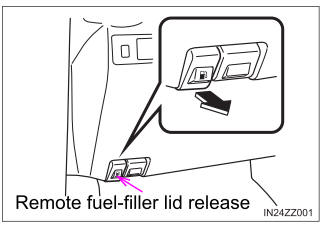
To open the fuel-filler lid, pull the remote fuel-filler lid release.