Toyota Yaris: Propeller Shaft Assembly / Installation
INSTALLATION
PROCEDURE
1. TEMPORARILY INSTALL PROPELLER SHAFT WITH CENTER BEARING ASSEMBLY
(a) Completely remove any oil or the like and clean the contact surfaces of the transfer assembly and propeller shaft with center bearing assembly.
(b) Completely remove any oil or the like and clean the contact surfaces of the rear differential carrier assembly and propeller shaft with center bearing assembly.
| (c) Align the matchmarks of the transfer assembly and propeller shaft with center bearing assembly. |
|
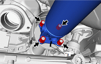
(d) Temporarily install the propeller shaft with center bearing assembly to the transfer assembly with the 4 nuts and 4 washers.
NOTICE:
Make sure there is no oil on the nuts and washers. If oil is found on any nut and washer, clean it before installation.
(e) When reusing the propeller shaft with center bearing assembly:
| (1) Align the matchmarks of the rear differential carrier assembly and propeller shaft with center bearing assembly. |
|
(f) When replacing the propeller shaft with center bearing assembly:
| (1) Align the alignment marks of the rear differential carrier assembly and propeller shaft with center bearing assembly. |
|
(g) Temporarily install the propeller shaft with center bearing assembly to the rear differential carrier assembly with the 4 nuts and 4 washers.
NOTICE:
Make sure there is no oil on the nuts and washers. If oil is found on any nut and washer, clean it before installation.
(h) Temporarily install the center support bearing and 2 center No. 2 support bearing washers with the 2 bolts.
NOTICE:
Make sure there is no oil on the bolts. If oil is found on any bolt, clean it before installation.
2. TIGHTEN PROPELLER SHAFT WITH CENTER BEARING ASSEMBLY
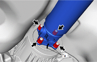
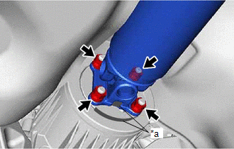
(a) Tighten the 4 nuts of the propeller shaft with center bearing assembly and transfer assembly to the torque specification.
Torque:
73.5 N·m {749 kgf·cm, 54 ft·lbf}
(b) Tighten the 4 nuts of the propeller shaft with center bearing assembly and rear differential carrier assembly to the torque specification.
Torque:
73.5 N·m {749 kgf·cm, 54 ft·lbf}
| (c) Check that the center line of the center support bearing housing is perpendicular to the axis of the propeller shaft. |
|
(d) Tighten the 2 bolts of the center support bearing to the torque specification.
Torque:
36.8 N·m {375 kgf·cm, 27 ft·lbf}
3. INSPECT AND ADJUST JOINT ANGLE
NOTICE:
Perform the measurement with a 4 post lift or pit so that the vehicle is supported by all 4 wheels as if it were on the ground.
(a) Before the angle measurement, stabilize each part by performing procedures like those described below.
(1) Rotate the propeller shaft several times by hand.
(2) Set the jack to the rear differential, and raise and lower the rear differential.
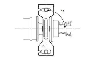
(b) Using SST and a straightedge, measure the angle of the transfer flange (angle D) and the angle of the intermediate shaft (angle A).
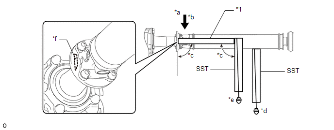
| *1 | Straightedge | - | - |
| *a | No. 1 Joint Angle | *b | D - A |
| *c | 90° | *d | Angle A |
| *e | Angle D | *f | Angle D Measurement Position |
SST: 09370-50010
NOTICE:
Make sure the straightedge and SST are at a right angle.
(1) Subtract the measured angle of the intermediate shaft (angle A) from the measured angle of the transfer flange (angle D) to obtain the No. 1 joint angle.
Standard No. 1 Joint Angle:
| Measurement Position | Angle |
|---|---|
| D - A | -1°56' +/- 1° |
(c) Using SST, measure the angle of the intermediate shaft (angle A) and the angle of the propeller shaft (angle B).
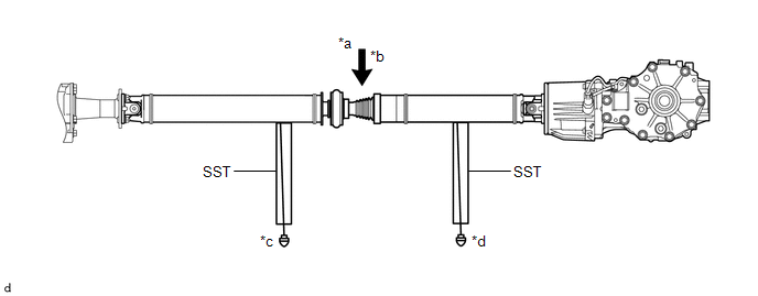
| *a | No. 2 Joint Angle | *b | A - B |
| *c | Angle A | *d | Angle B |
SST: 09370-50010
(1) Subtract the measured angle of the propeller shaft (angle B) from the measured angle of the intermediate shaft (angle A) to obtain the No. 2 joint angle.
Standard No. 2 Joint Angle:
| Measurement Position | Angle |
|---|---|
| A - B | 1°00' +/- 1° |
(d) Using SST, measure the angle of the propeller shaft (angle B) and the angle of the rear differential (angle C).
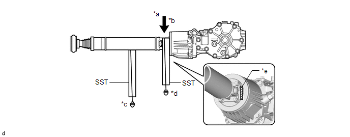
| *a | No. 3 Joint Angle | *b | B - C |
| *c | Angle B | *d | Angle C |
| *e | Angle C Measurement Position | - | - |
SST: 09370-50010
(1) Subtract the measured angle of the rear differential (angle C) from the measured angle of the propeller shaft (angle B) to obtain the No. 3 joint angle.
Standard No. 3 Joint Angle:
| Measurement Position | Angle |
|---|---|
| B - C | 2°50' +/- 1° |
(e) If the measured angle of the propeller shaft with center bearing assembly is not within the specified range, or there is vibration or noise, use the following procedure to adjust the propeller shaft with center bearing assembly.
(1) Support the propeller shaft with center bearing assembly with a jack.
(2) Remove the 2 center support bearing mounting bolts.
(3) Slowly lower the jack and separate the center support bearing.
(4) Select an appropriate adjusting washer thickness from the table below, and obtain a washer set.
Adjusting Washer:
| Part No. | Thickness |
|---|---|
| 90201-10123 | 2.0 mm (0.0787 in.) |
| 90201-10081 | 4.5 mm (0.177 in.) |
| 90201-10083 | 6.5 mm (0.256 in.) |
| 90201-10084 | 9.0 mm (0.354 in.) |
| 90201-10085 | 11.0 mm (0.433 in.) |
NOTICE:
- Use washers of the same thickness on the left and right sides.
- Do not use 2 or more washers stacked together.
4. INSTALL FRONT NO. 1 FLOOR HEAT INSULATOR SUB-ASSEMBLY
(a) Install the front No. 1 floor heat insulator sub-assembly to the vehicle body with the 2 nuts.
Torque:
5.0 N·m {51 kgf·cm, 44 in·lbf}
5. INSTALL FRONT FLOOR COVER LH
(a) Engage the 6 clamps to install the front floor cover LH to the vehicle body.
(b) Install the bolt and 3 clips.
Torque:
7.5 N·m {76 kgf·cm, 66 in·lbf}
6. INSTALL FRONT FLOOR COVER RH
HINT:
Use the same procedure as for the LH side.
7. INSTALL FRONT EXHAUST PIPE ASSEMBLY
Click here

 Inspection
INSPECTION PROCEDURE 1. INSPECT PROPELLER SHAFT WITH CENTER BEARING ASSEMBLY (a) Using a dial indicator, measure the propeller shaft runout for the front side...
 Propeller Shaft System
Problem Symptoms TablePROBLEM SYMPTOMS TABLE HINT: Use the table below to help determine the cause of problem symptoms. If multiple suspected areas are listed, the potential causes of the symptoms are listed in order of probability in the "Suspected Area" column of the table...
Other information:
Toyota Yaris XP210 (2020-2026) Reapir and Service Manual: Reassembly
REASSEMBLY CAUTION / NOTICE / HINT HINT: Use the same procedure for the LH side and RH side. The following procedure is for the LH side. PROCEDURE 1. INSTALL HOLE PLUG (a) Install the 2 hole plugs. 2. INSTALL HOLE PLUG (a) Install the 3 hole plugs...
Toyota Yaris XP210 (2020-2026) Reapir and Service Manual: Inspection
INSPECTION PROCEDURE 1. INSPECT REVERSE IDLER GEAR THRUST CLEARANCE (a) Using a feeler gauge, measure the reverse idler gear thrust clearance. Standard Clearance: 0.40 to 1.05 mm (0.0157 to 0.0413 in.) Maximum Clearance: 1.05 mm (0.0413 in.) If the clearance exceeds the maximum, replace the reverse idler gear, needle roller bearing, and reverse idler gear shaft...
Categories
- Manuals Home
- Toyota Yaris Owners Manual
- Toyota Yaris Service Manual
- To Set Speed
- Power Integration No.1 System Missing Message (B235287,B235587,B235787-B235987)
- Fuse Panel Description
- New on site
- Most important about car
Turning the Engine Off
Stop the vehicle completely. Manual transaxle: Shift into neutral and set the parking brake.Automatic transaxle: Shift the selector lever to the P position and set the parking brake.
Press the push button start to turn off the engine. The ignition position is off.