Toyota Yaris: Transfer Assembly / Disassembly
DISASSEMBLY
CAUTION / NOTICE / HINT
NOTICE:
Before installation of each part, thoroughly clean and dry it. Then apply grease or oil as necessary. Do not use alkaline chemicals to clean aluminum parts, rubber parts or precoated bolts. Also, do not use non-residue solvent or other cleaning oils to clean O-rings, oil seals or rubber parts.
PROCEDURE
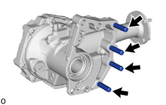
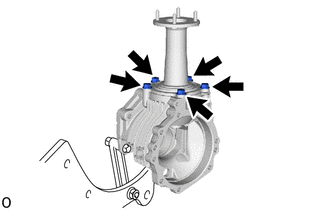
1. REMOVE TRANSFER AND TRANSAXLE SETTING STUD BOLT
| (a) Using 2 nuts, remove the 4 transfer and transaxle setting stud bolts. |
|
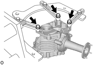
2. SECURE TRANSFER ASSEMBLY
| (a) Secure the transfer assembly to the overhaul attachment. |
|
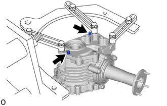
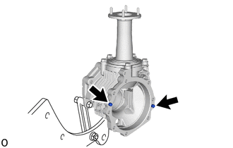
3. REMOVE TRANSFER CASE STRAIGHT PIN
| (a) Remove the 2 transfer case straight pins. |
|
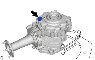
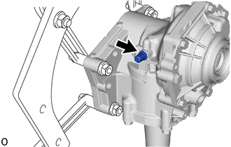
4. REMOVE NO. 1 TRANSFER CASE PLUG
| (a) Remove the No. 1 transfer case plug and gasket. |
|
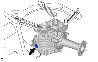
5. REMOVE TRANSFER DRAIN PLUG
| (a) Using a 10 mm socket hexagon wrench, remove the transfer drain plug and gasket. |
|
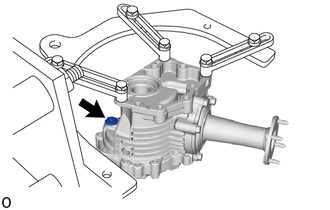
6. REMOVE TRANSFER FILLER PLUG
| (a) Using a 10 mm socket hexagon wrench, remove the transfer filler plug and gasket. |
|
7. REMOVE TRANSFER CASE BREATHER PLUG
| (a) Using a chisel and hammer, slightly pry out the transfer case breather plug. |
|
(b) Using a screwdriver, lightly pry up and remove the transfer case breather plug.
8. REMOVE TRANSFER CASE OIL SEAL
Click here

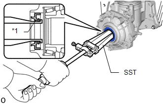
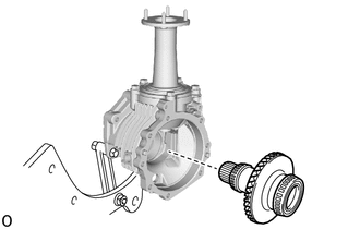
9. REMOVE TRANSFER CASE OIL SEAL RH
| (a) Using SST, remove the transfer case oil seal RH from the No. 1 transfer case cover. SST: 09308-00010 NOTICE: Do not scratch the press-fitting surface of the transfer case oil seal RH. |
|
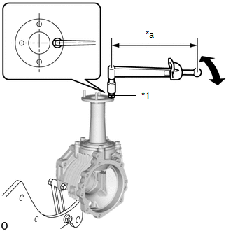
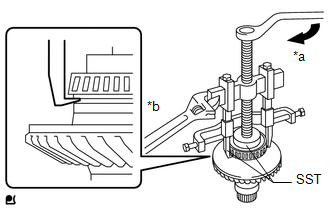
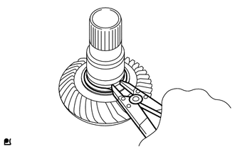
10. INSPECT TOTAL PRELOAD
| (a) Install the double nut to the transfer output shaft stud bolt and set the torque wrench into place. HINT: Adjust the double nut until the torque wrench is straight. |
|
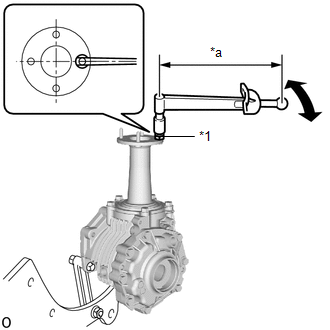
(b) Using a torque wrench, check the total preload (starting torque) with the teeth of the drive pinion and ring gear in contact.
Torque:
Total preload (starting torque) :
0.87-2.85 N·m {8.88-29.06 kgf·cm, 7.71-25.22 in·lbf}
HINT:
-
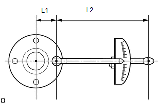
When using a torque wrench after changing its effective length, determine the reading of the torque wrench. Formula T'=T x L2/(L1+L2)
T'
Reading of torque wrench (N*m (kgf*cm, ft.*lbf))
T
Driven pinion preload (N*m (kgf*cm, ft.*lbf))
L1
Distance from center of transfer output shaft to center of stud bolt (cm (in.))
L2
Length of torque wrench (cm (in.))

- Distance from center of transfer output shaft to center of stud bolt (effective length of 33.9 mm) when using a torque wrench (effective length of 160 mm): 0.70 to 2.29 N*m (7.14 to 23.35 kgf*cm, 0.52 to 1.68 ft.*lbf)
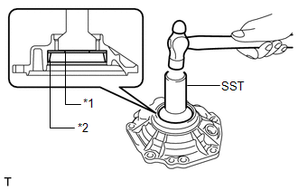
11. INSPECT RING GEAR BACKLASH
| (a) Insert a dial indicator through the No. 2 transfer case plug hole, and set it perpendicular to the edge of a ring gear tooth. If the backlash is not within the specified range, adjust the backlash or repair as necessary. |
|
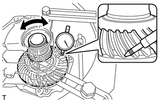
(b) While securing the transfer output shaft by hand, rotate the transfer ring gear mounting case forward and backward by hand and measure the backlash of the ring gear and driven pinion.
Standard backlash:
0.10 to 0.20 mm (0.00394 to 0.00787 in.)
NOTICE:
Measure the ring gear at 3 or more locations.
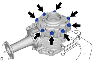
12. REMOVE NO. 1 TRANSFER CASE COVER
| (a) Remove the 8 bolts. |
|
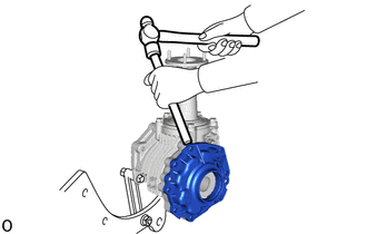
| (b) Using a brass bar and hammer, remove the No. 1 transfer case cover from the transfer case. NOTICE:
HINT: To prevent the No. 1 transfer case cover from falling, leave 2 of the bolts screwed in by 5 or 6 threads. |
|
13. REMOVE TRANSFER RING GEAR
| (a) Remove the transfer ring gear from the transfer case. |
|
14. REMOVE TRANSFER CASE STRAIGHT PIN
| (a) Remove the 2 transfer case straight pins from the transfer case. |
|
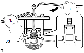
15. INSPECT DRIVEN PINION PRELOAD
| (a) Install the double nut to the transfer output shaft stud bolt and set the torque wrench into place. HINT: Adjust the double nut until the torque wrench is straight. |
|
(b) Using a torque wrench, check the total preload (starting torque) with the teeth of the drive pinion and ring gear in contact.
Torque:
Driven pinion preload (starting torque) :
0.39-2.21 N·m {3.98-22.53 kgf·cm, 3.46-19.55 in·lbf}
HINT:
-
When using a torque wrench after changing its effective length, determine the reading of the torque wrench. Formula T'=T x L2/(L1+L2)
T'
Reading of torque wrench (N*m (kgf*cm, ft.*lbf))
T
Driven pinion preload (N*m (kgf*cm, ft.*lbf))
L1
Distance from center of transfer output shaft to center of stud bolt (cm (in.))
L2
Length of torque wrench (cm (in.))
- Distance from center of transfer output shaft to center of stud bolt (effective length of 33.9 mm) when using a torque wrench (effective length of 160 mm): 0.32 to 1.77 N*m (3.27 to 18.04 kgf*cm, 2.84 to 15.66 in.*lbf)
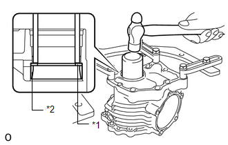
16. REMOVE REAR TRANSFER OUTPUT SHAFT SUB-ASSEMBLY
| (a) Remove the 5 bolts and rear transfer output shaft sub-assembly from the transfer case. |
|
(b) Mount the rear transfer output shaft sub-assembly in a vise between aluminum plates.
NOTICE:
Do not overtighten the vise.
| (c) Using SST and a hammer, unstake the transfer gear nut. SST: 09930-00010 NOTICE:
|
|
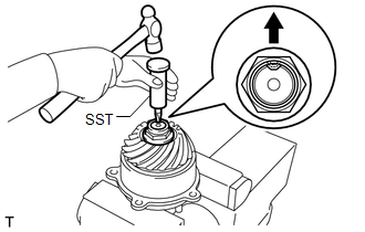
(d) Using a 30 mm socket wrench, remove the transfer gear nut.
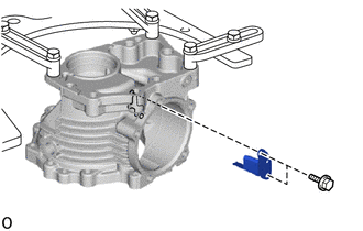
17. REMOVE BREATHER OIL DEFLECTOR
| (a) Remove the 2 bolts and breather oil deflector from the transfer case. |
|
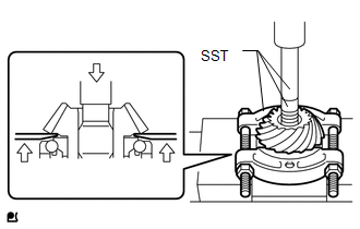
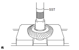
18. REMOVE TRANSFER DRIVEN PINION
| (a) Using SST and a press, remove the transfer driven pinion from the rear transfer output shaft sub-assembly. SST: 09950-00020 SST: 09950-60011 09951-00240 SST: 09950-70010 09951-07100 NOTICE: Support the front transfer driven pinion bearing as shown in the illustration to avoid placing stress on the outer race. |
|
19. REMOVE REAR TRANSFER OUTPUT SHAFT DUST DEFLECTOR
| (a) Using SST and a press, remove the rear transfer output shaft dust deflector from the rear transfer output shaft sub-assembly. SST: 09950-00020 |
|
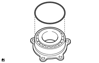
20. REMOVE FRONT TRANSFER DRIVEN PINION BEARING
| (a) Using SST and a press, remove the front transfer driven pinion bearing from the transfer driven pinion. SST: 09950-00020 SST: 09950-60011 09951-00410 SST: 09950-70010 09951-07100 NOTICE: Support the front transfer driven pinion bearing as shown in the illustration to avoid placing stress on the outer race. |
|
| (b) Remove the O-ring from the front transfer driven pinion bearing. |
|
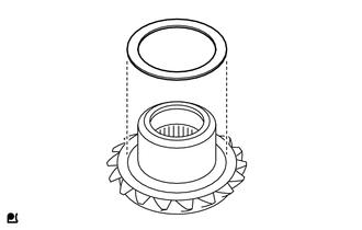
21. REMOVE TRANSFER OUTPUT SHAFT WASHER
| (a) Remove the transfer output shaft washer from the transfer driven pinion. |
|
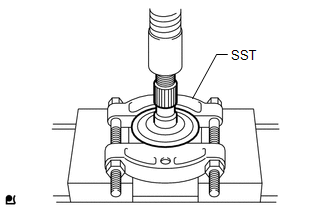
22. REMOVE RING GEAR MOUNTING CASE BEARING RH
| (a) Using SST, remove the ring gear mounting case bearing RH (inner race) from the transfer ring gear mounting case. SST: 09950-40011 09951-04010 09952-04010 09953-04030 09954-04010 09955-04061 09957-04010 09958-04011 SST: 09950-60011 09951-00540 NOTICE:
|
|
| (b) Using SST and a hammer, remove the No. 2 transfer ring gear mounting case washer and ring gear mounting case bearing RH (outer race) from the No. 1 transfer case cover. SST: 09310-35010 |
|
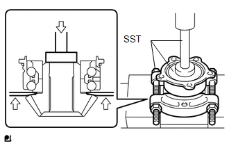
23. REMOVE RING GEAR MOUNTING CASE BEARING LH
| (a) Using SST, remove the ring gear mounting case bearing LH (inner race) from the transfer ring gear mounting case. SST: 09950-00020 SST: 09950-00030 NOTICE:
|
|
| (b) Using SST and a hammer, remove the No. 1 ring gear mounting case washer and ring gear mounting case bearing LH (outer race) from the transfer case. SST: 09636-20010 |
|
24. REMOVE SHAFT SNAP RING
| (a) Using a snap ring expander, remove the shaft snap ring. |
|
25. REMOVE TRANSFER RING GEAR MOUNTING CASE
| (a) Using SST and a press, remove the transfer ring gear mounting case from the transfer ring gear. SST: 09950-60011 09951-00400 |
|
 Removal
REMOVAL CAUTION / NOTICE / HINT The necessary procedures (adjustment, calibration, initialization, or registration) that must be performed after parts are removed and installed, or replaced during the transfer assembly removal/installation are shown below...
 Reassembly
REASSEMBLY CAUTION / NOTICE / HINT NOTICE: Steps 9 to 16 are temporary reassembly procedures for adjustment purposes. PROCEDURE 1. INSTALL TRANSFER RING GEAR MOUNTING CASE (a) Using SST and a press, press the transfer ring gear mounting case into the transfer ring gear...
Other information:
Toyota Yaris XP210 (2020-2026) Reapir and Service Manual: Door Control Receiver
ComponentsCOMPONENTS ILLUSTRATION *1 DOOR CONTROL RECEIVER - - N*m (kgf*cm, ft.*lbf): Specified torque - - RemovalREMOVAL PROCEDURE 1. REMOVE DECK TRIM SIDE PANEL ASSEMBLY Click here 2. REMOVE DOOR CONTROL RECEIVER NOTICE: Do not drop, strike or otherwise subject the door control receiver to impact...
Toyota Yaris XP210 (2020-2026) Reapir and Service Manual: Turbocharger/Supercharger Wastegate Solenoid "A" Circuit Open (P024313)
DESCRIPTION The waste gate valve is built into the turbine housing and is operated by the vacuum regulating valve assembly. The ECM uses duty control to open and close the vacuum regulating valve assembly. The amount of opening is controlled according to the operation status...
Categories
- Manuals Home
- Toyota Yaris Owners Manual
- Toyota Yaris Service Manual
- Engine Start Function When Key Battery is Dead
- Brake System Control Module "A" System Voltage System Voltage Low (C137BA2)
- Fuel Gauge
- New on site
- Most important about car
Fuel Gauge
The fuel gauge shows approximately how much fuel is remaining in the tank when the ignition is switched ON. We recommend keeping the tank over 1/4 full.
