Toyota Yaris: Input Shaft / Disassembly
DISASSEMBLY
PROCEDURE
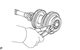
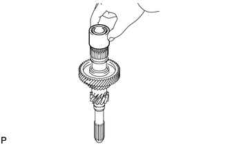
1. REMOVE INPUT SHAFT REAR BEARING SHAFT SNAP RING
| (a) Using a snap ring expander, remove the input shaft rear bearing shaft snap ring from the input shaft. |
|
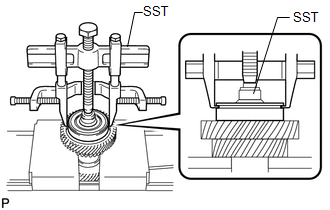
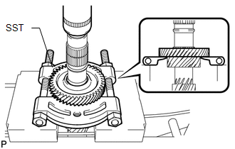
2. REMOVE INPUT SHAFT REAR RADIAL BALL BEARING
| (a) Using SST, remove the input shaft rear radial ball bearing from the input shaft. SST: 09950-40011 09951-04020 09952-04010 09953-04020 09954-04010 09955-04011 09957-04010 09958-04011 SST: 09631-20031 |
|
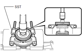
3. REMOVE 6TH DRIVE GEAR
| (a) Using SST and a press, remove the 6th drive gear from the input shaft. SST: 09950-00020 |
|
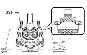
4. REMOVE 3RD DRIVE GEAR
| (a) Using SST and a press, remove the 3rd drive gear from the input shaft. SST: 09950-00020 |
|
| (b) Remove the spacer from the input shaft. |
|
5. REMOVE 4TH DRIVE GEAR
| (a) Using SST and a press, remove the 4th drive gear from the input shaft. SST: 09950-00020 |
|
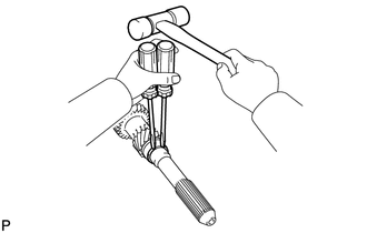
6. REMOVE INPUT SHAFT SNAP RING
| (a) Using 2 screwdrivers and a hammer, remove the input shaft snap ring from the input shaft. |
|
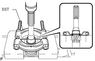
7. REMOVE INPUT SHAFT FRONT BEARING INNER RACE
| (a) Using SST and a press, remove the input shaft front bearing inner race from the input shaft. SST: 09950-00020 |
|
 Components
C..
 Inspection
INSPECTION PROCEDURE 1. INSPECT INPUT SHAFT (a) Check the input shaft for wear and damage.
(b) Using a dial indicator, measure the input shaft runout...
Other information:
Toyota Yaris XP210 (2020-2026) Reapir and Service Manual: Turbocharger/Supercharger Bypass Valve "A" Actuator Stuck Closed (P23AA73)
DESCRIPTION Refer to DTC P003312. Click here DTC No. Detection Item DTC Detection Condition Trouble Area MIL Note P23AA73 Turbocharger/Supercharger Bypass Valve "A" Actuator Stuck Closed Either of the following conditions is met (1 trip detection logic)...
Toyota Yaris XP210 (2020-2026) Reapir and Service Manual: Parts Location
P..
Categories
- Manuals Home
- Toyota Yaris Owners Manual
- Toyota Yaris Service Manual
- Adjustment
- How to connect USB port/Auxiliary jack
- Engine Start Function When Key Battery is Dead
- New on site
- Most important about car
Keys

To use the auxiliary key, press the knob and pull out the auxiliary key from the smart key.
