Toyota Yaris: Wireless Door Lock Control System / Terminals Of Ecu
TERMINALS OF ECU
CHECK POWER DISTRIBUTION BOX ASSEMBLY AND MAIN BODY ECU (MULTIPLEX NETWORK BODY ECU)
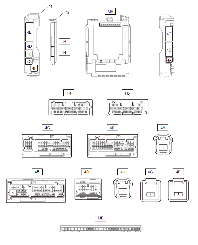
| *1 | Power Distribution Box Assembly | *2 | Main Body ECU (Multiplex Network Body ECU) |
(a) Remove the main body ECU (multiplex network body ECU) from the power distribution box assembly.
Click here

(b) Reconnect the power distribution box assembly connector.
(c) Measure the voltage and resistance according to the value(s) in the table below.
HINT:
Measure the values on the wire harness side with the connectors connected.
| Terminal No. (Symbol) | Terminal Description | Condition | Specified Condition |
|---|---|---|---|
| MB-13 (GND1) - Body ground | Ground | Always | Below 1 Ω |
| MB-26 (BECU) - Body ground | Auxiliary battery power supply | Always | 11 to 14 V |
| MB-27 (IGR) - Body ground | IG power supply | Ignition switch ON | 11 to 14 V |
(d) Install the main body ECU (multiplex network body ECU) to the power distribution box assembly.
Click here

(e) Measure the voltage and check for pulses according to the value(s) in the table below.
| Terminal No. (Symbol) | Terminal Description | Condition | Specified Condition |
|---|---|---|---|
| 4E-5 (FRCY) - Body ground | Front door courtesy light switch (for RH) input | Front door RH open | Below 1 V |
| Front door RH closed | 11 to 14 V | ||
| 4E-3 (FLCY) - Body ground | Front door courtesy light switch (for LH) input | Front door LH open | Below 1 V |
| Front door LH closed | 11 to 14 V | ||
| 4E-2 (BCTY) - Body ground | Back door courtesy light switch input | Back door closed | Below 1 V |
| Back door open | 11 to 14 V | ||
| 4E-39 (TR+) - Body ground | Back door lock motor drive output | Back door closed → open | Below 1 V → 11 to 14 V → Below 1 V |
| 4C-36 (ACT-) - Body ground | Door lock motor unlock drive output | Door control switch or driver door key cylinder off → on (unlock) | Below 1 V → 11 to 14 V → Below 1 V |
| 4B-34 (ACT+) - Body ground | Door lock motor lock drive output | Door control switch or driver door key cylinder off → on (lock) | Below 1 V → 11 to 14 V → Below 1 V |
| 4B-19 (ACT+) - Body ground | |||
| H4-3 (LSFR) - Body ground | Front door RH unlock detection switch input | Front door RH unlocked | Below 1 V |
| Front door RH locked | Pulse generation | ||
| H4-9 (LSFL) - Body ground | Front door LH unlock detection switch input | Front door LH unlocked | Below 1 V |
| Front door LH locked | Pulse generation | ||
| H4-28 (L2) - Body ground | Driver door key-linked lock input | Driver door key cylinder turned to lock | Below 1 V |
| H4-28 (L2) - Body ground | Driver door key-linked lock input | Driver door key cylinder not turned | Pulse generation |
| H4-4 (UL3) - Body ground | Driver door key-linked unlock input | Driver door key cylinder turned to unlock | Below 1 V |
| H4-4 (UL3) - Body ground | Driver door key-linked unlock input | Driver door key cylinder not turned | Pulse generation |
| 4D-7 (BZR) - Body ground | Wireless door lock buzzer output | Active Test Wireless Buzzer on | Pulse generation |
| Active Test Wireless Buzzer off | Below 1 V |
CHECK CERTIFICATION ECU (SMART KEY ECU ASSEMBLY)
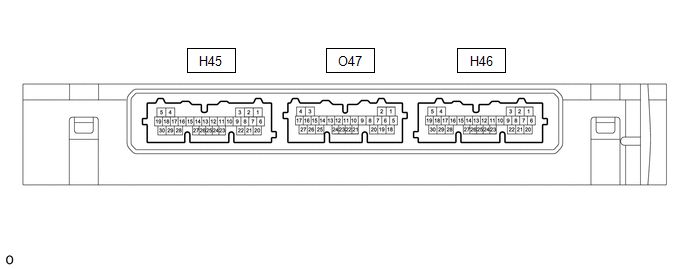
(a) Disconnect the H46 certification ECU (smart key ECU assembly) connector.
(b) Measure the voltage and resistance according to the value(s) in the table below.
| Terminal No. (Symbol) | Terminal Description | Condition | Specified Condition |
|---|---|---|---|
| H46-29 (E) - Body ground | Ground | Always | Below 1 Ω |
| H46-6 (+B) - Body ground | Auxiliary battery power supply | Always | 11 to 14 V |
(c) Reconnect the H46 certification ECU (smart key ECU assembly) connector.
(d) Measure the voltage and check for pulses according to the value(s) in the table below.
| Tester Connection | Terminal Description | Condition | Specified Condition |
|---|---|---|---|
| O47-21 (RCO) - H46-29 (E) | Output to smart door control receiver assembly (Power supply for smart door control receiver assembly. Certification ECU (smart key ECU assembly) outputs 5 V when receiver starts operating.) | Proceed:
| Pulse generation (See waveform 1) |
| O47-12 (CSEL) - H46-29 (E) | Communication channel switching circuit | Proceed:
| No pulse generation → Pulse generation |
| O47-11 (RDAM) - H46-29 (E) | Smart door control receiver assembly communication circuit | Proceed:
| Pulse generation (See waveform 2) |
(e) Using an oscilloscope, check waveform 1.
NOTICE:
The oscilloscope waveform shown in the illustration is an example for reference only. Noise, chattering, etc. are not shown.
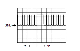
| *a | Before lock or unlock switch of electrical key transmitter sub-assembly pressed |
| *b | After lock or unlock switch of electrical key transmitter sub-assembly pressed |
| Item | Content |
|---|---|
| Tester Connection | O47-21 (RCO) - H46-29 (E) |
| Tool Setting | 2 V/DIV., 500 ms./DIV. |
| Condition | Procedure:
|
(f) Using an oscilloscope, check waveform 2.
NOTICE:
The oscilloscope waveform shown in the illustration is an example for reference only. Noise, chattering, etc. are not shown.
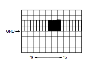
| *a | Before lock or unlock switch of electrical key transmitter sub-assembly pressed |
| *b | After lock or unlock switch of electrical key transmitter sub-assembly pressed |
| Item | Content |
|---|---|
| Tester Connection | O47-11 (RDAM) - H46-29 (E) |
| Tool Setting | 5 V/DIV., 500 ms./DIV. |
| Condition | Procedure:
|
 Problem Symptoms Table
PROBLEM SYMPTOMS TABLE HINT:
Use the table below to help determine the cause of problem symptoms. If multiple suspected areas are listed, the potential causes of the symptoms are listed in order of probability in the "Suspected Area" column of the table...

Other information:
Toyota Yaris XP210 (2020-2026) Owner's Manual: Key Battery Replacement
If the buttons on the smart key are inoperable and the operation indicator light does not flash, the battery may be dead. Replace with a new battery before the smart key becomes unusable. The following conditions indicate that the battery power is low: The KEY indicator light (green) flashes in the combination meter for about 30 seconds after the engine is switched OFF...
Toyota Yaris XP210 (2020-2026) Owner's Manual: Limitations to front/near front collision detection
T..
Categories
- Manuals Home
- Toyota Yaris Owners Manual
- Toyota Yaris Service Manual
- Immobilizer System
- Maintenance
- Fuse Panel Description
- New on site
- Most important about car
Fuel Gauge
The fuel gauge shows approximately how much fuel is remaining in the tank when the ignition is switched ON. We recommend keeping the tank over 1/4 full.
