Toyota Yaris: Rear Drive Shaft Assembly / Reassembly
REASSEMBLY
CAUTION / NOTICE / HINT
NOTICE:
- When using a vise, place aluminum plates between the part and vise.
- When using a vise, do not overtighten it.
HINT:
- Use the same procedure for the RH side and LH side.
- The following procedure is for the LH side.
PROCEDURE
1. INSTALL REAR DRIVE SHAFT DUST COVER
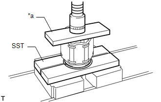
| (a) Using SST, a steel plate and a press, install a new rear drive shaft dust cover to the rear drive shaft inboard joint assembly. SST: 09527-10011 NOTICE:
|
|
2. INSTALL REAR DRIVE SHAFT INBOARD JOINT ASSEMBLY
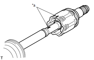
(a) Wrap the spline of the rear drive outboard joint shaft assembly with protective tape to prevent the boot from being damaged.
(b) Install new parts to the rear drive outboard joint shaft assembly in the following order:
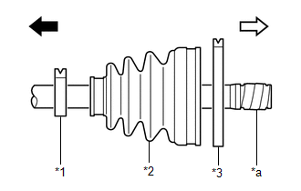
| *1 | Rear Drive Shaft Inboard Joint Boot Clamp |
| *2 | Rear Drive Shaft Inboard Joint Boot |
| *3 | Rear No. 2 Drive Shaft Inboard Joint Boot Clamp |
| *a | Protective Tape |
 | Outboard Joint Side |
 | Inboard Joint Side |
(1) Rear drive shaft inboard joint boot clamp
(2) Rear drive shaft inboard joint boot
(3) Rear No. 2 drive shaft inboard joint boot clamp
(c) Remove the protective tape.
| (d) Align the matchmarks and install the tripod joint to the rear drive outboard joint shaft assembly. NOTICE: Face the serrated side of the tripod joint outward and install it to the outboard joint end. |
|
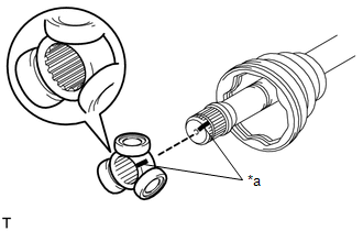
(e) Using a brass bar and a hammer, install the tripod joint to the rear drive outboard joint shaft assembly.
NOTICE:
- Do not tap the rollers.
- Keep the tripod joint free of foreign matter.
- Make sure to install the tripod joint in the correct direction.
| (f) Using a snap ring expander, install a new rear drive shaft snap ring to the rear drive outboard joint shaft assembly. |
|
(g) Pack the rear drive shaft inboard joint assembly and rear drive shaft inboard joint boot with grease.
Standard Grease Capacity:
134 to 144 g (4.73 to 5.08 oz.)
| (h) Align the matchmarks and install the rear drive shaft inboard joint assembly to the rear drive outboard joint shaft assembly. |
|
3. INSTALL REAR DRIVE SHAFT INBOARD JOINT BOOT
(a) Install the rear drive shaft inboard joint boot to the rear drive shaft inboard joint assembly.
NOTICE:
- Keep the grooves free of grease.
- Keep the inside of the rear drive shaft inboard joint boot free of foreign matter.
| (b) Check whether the dimension (A) of each drive shaft is within specification. Dimension (A):
|
|
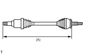
(c) While keeping dimension (A) within the specified length, equalize the pressure within the inboard joint with atmospheric pressure by slightly lifting the rear drive shaft inboard joint boot from the rear drive shaft inboard joint assembly.
4. INSTALL REAR DRIVE SHAFT INBOARD JOINT BOOT CLAMP
(a) Install the rear drive shaft inboard joint boot clamp to the rear drive shaft inboard joint boot.
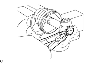
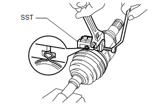
| (b) Place SST onto the rear drive shaft inboard joint boot clamp, press it against the boot and slightly tighten SST. SST: 09521-24010 |
|
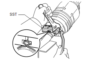
(c) Tighten SST so that the rear drive shaft inboard joint boot clamp is pinched.
NOTICE:
Do not overtighten SST.
(d) Remove SST.
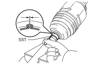
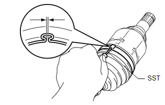
| (e) Using SST, measure the clearance of the rear drive shaft inboard joint boot clamp. SST: 09240-00021 Standard Clearance: Below 1.3 mm (0.0512 in.) If the clearance is not as specified, retighten SST. |
|
5. INSTALL REAR NO. 2 DRIVE SHAFT INBOARD JOINT BOOT CLAMP
(a) Install the rear No. 2 drive shaft inboard joint boot clamp to the rear drive shaft inboard joint boot.
| (b) Place SST onto the rear No. 2 drive shaft inboard joint boot clamp, press it against the boot and slightly tighten SST. SST: 09521-24010 |
|
(c) Tighten SST so that the rear No. 2 drive shaft inboard joint boot clamp is pinched.
NOTICE:
Do not overtighten SST.
(d) Remove SST.
| (e) Using SST, measure the clearance of the rear No. 2 drive shaft inboard joint boot clamp. SST: 09240-00021 Standard Clearance: Below 2.1 mm (0.0827 in.) If the clearance is not as specified, retighten SST. |
|
6. INSPECT REAR DRIVE SHAFT ASSEMBLY
Click here

 Inspection
INSPECTION PROCEDURE 1. INSPECT REAR DRIVE SHAFT ASSEMBLY (a) Check that there is no excessive play in the radial direction of the outboard joint.
(b) Check that the inboard joint slides smoothly in the thrust direction...
 Installation
INSTALLATION CAUTION / NOTICE / HINT HINT:
Use the same procedure for the RH side and LH side.
The following procedure is for the LH side.
PROCEDURE 1...
Other information:
Toyota Yaris XP210 (2020-2026) Reapir and Service Manual: On-vehicle Inspection
ON-VEHICLE INSPECTION PROCEDURE 1. INSPECT AUTOMATIC LIGHT CONTROL SENSOR (a) Check the wire harness. (1) Disconnect the automatic light control sensor. (2) Measure the voltage according to the value(s) in the table below. Standard Voltage: Tester Connection Switch Condition Specified Condition H78-1 (CLTB) - H78-2 (CLTE) Ignition switch on (IG) 11 to 14 V If the specified condition is not met, replace the vehicle wire harness...
Toyota Yaris XP210 (2020-2026) Reapir and Service Manual: Removal
REMOVAL CAUTION / NOTICE / HINT HINT: When the cable is disconnected / reconnected to the auxiliary battery terminal, systems temporarily stop operating. However, each system has a function that completes learning the first time the system is used. Learning completes when vehicle is driven Effect/Inoperative Function When Necessary Procedures are not Performed Necessary Procedures Link Lane tracing assist system Drive the vehicle straight ahead at 35 km/h (22 mph) or more for 5 seconds or more...
Categories
- Manuals Home
- Toyota Yaris Owners Manual
- Toyota Yaris Service Manual
- Maintenance
- Diagnostic Trouble Code Chart
- How to connect USB port/Auxiliary jack
- New on site
- Most important about car
Fuel Gauge
The fuel gauge shows approximately how much fuel is remaining in the tank when the ignition is switched ON. We recommend keeping the tank over 1/4 full.
