Toyota Yaris: Rear Drive Shaft Assembly / Inspection
INSPECTION
PROCEDURE
1. INSPECT REAR DRIVE SHAFT ASSEMBLY
| (a) Check that there is no excessive play in the radial direction of the outboard joint. |
|
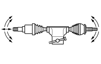
(b) Check that the inboard joint slides smoothly in the thrust direction.
(c) Check that there is no excessive play in the radial direction of the inboard joint.
(d) Check the boots for damage.
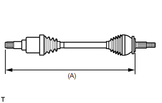
| (e) Check whether each drive shaft dimension (A) is within specification. Dimension (A):
NOTICE: Keep the drive shaft assembly level during inspection. |
|
 Disassembly
DISASSEMBLY CAUTION / NOTICE / HINT NOTICE:
When using a vise, place aluminum plates between the part and vise.
When using a vise, do not overtighten it...
 Reassembly
REASSEMBLY CAUTION / NOTICE / HINT NOTICE:
When using a vise, place aluminum plates between the part and vise.
When using a vise, do not overtighten it...
Other information:
Toyota Yaris XP210 (2020-2026) Reapir and Service Manual: Utility
UTILITY Front Beam Axis Adjustment HINT: Front Beam Axis Adjustment is used to calibrate the beam axis of millimeter wave radar sensor assembly. (a) Perform Front Beam Axis Adjustment according to the display on the GTS. Body Electrical > Front Radar Sensor > Utility Tester Display Front Beam Axis Adjustment Front Beam Axis Misalignment Reading HINT: Front Beam Axis Misalignment Reading is used to check the amount of misalignment of the millimeter wave radar sensor assembly...
Toyota Yaris XP210 (2020-2026) Reapir and Service Manual: Reassembly
REASSEMBLY PROCEDURE 1. INSTALL CONTROL SHAFT COVER OIL SEAL (a) Using SST and a hammer, install a control shaft cover oil seal to the control shaft cover. SST: 09307-12010 Drive in Depth: 0 to 0.5 mm (0 to 0.0197 in.) (b) Coat a new control shaft cover oil seal lip with MP grease...
Categories
- Manuals Home
- Toyota Yaris Owners Manual
- Toyota Yaris Service Manual
- Key Battery Replacement
- How to connect USB port/Auxiliary jack
- Auto Lock/Unlock Function
- New on site
- Most important about car
Fuel-Filler Lid and Cap
WARNING
When removing the fuel-filler cap, loosen the cap slightly and wait for any hissing to stop, then remove it
Fuel spray is dangerous. Fuel can burn skin and eyes and cause illness if ingested. Fuel spray is released when there is pressure in the fuel tank and the fuel-filler cap is removed too quickly.