Toyota Yaris: Rear Drive Shaft Assembly / Disassembly
DISASSEMBLY
CAUTION / NOTICE / HINT
NOTICE:
- When using a vise, place aluminum plates between the part and vise.
- When using a vise, do not overtighten it.
HINT:
- Use the same procedure for the RH side and LH side.
- The following procedure is for the LH side.
PROCEDURE
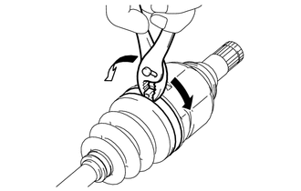
1. SEPARATE REAR NO. 2 DRIVE SHAFT INBOARD JOINT BOOT CLAMP
| (a) Using pliers, separate the rear No. 2 drive shaft inboard joint boot clamp as shown in the illustration. |
|
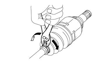
2. SEPARATE REAR DRIVE SHAFT INBOARD JOINT BOOT CLAMP
| (a) Using pliers, separate the rear drive shaft inboard joint boot clamp as shown in the illustration. |
|
3. SEPARATE REAR DRIVE SHAFT INBOARD JOINT BOOT
(a) Separate the rear drive shaft inboard joint boot from the rear drive shaft inboard joint assembly.
4. REMOVE REAR DRIVE SHAFT INBOARD JOINT ASSEMBLY
(a) Remove any old grease from the rear drive shaft inboard joint assembly.
| (b) Put matchmarks on the rear drive shaft inboard joint assembly and rear drive outboard joint shaft assembly. NOTICE: Do not use a punch to make the matchmarks. |
|
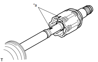
(c) Remove the rear drive shaft inboard joint assembly from the rear drive outboard joint shaft assembly.
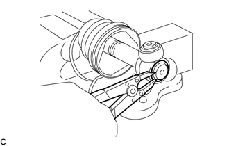
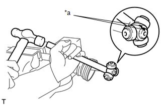
| (d) Using a snap ring expander, remove the rear drive shaft snap ring from the rear drive outboard joint shaft assembly. |
|
| (e) Put matchmarks on the rear drive outboard joint shaft assembly and tripod joint. NOTICE: Do not use a punch to make the matchmarks. |
|
(f) Using a brass bar and a hammer, tap out the tripod joint from the rear drive outboard joint shaft assembly.
NOTICE:
- Do not tap the rollers.
- Do not drop the tripod joint.
5. REMOVE REAR DRIVE SHAFT INBOARD JOINT BOOT
(a) Remove the rear No. 2 drive shaft inboard joint boot clamp, rear drive shaft inboard joint boot and rear drive shaft inboard joint boot clamp.
6. REMOVE REAR DRIVE SHAFT DUST COVER
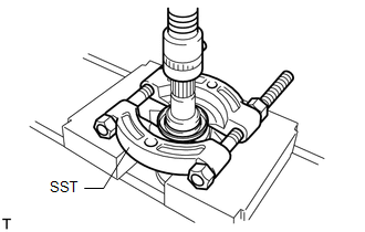
| (a) Using SST and a press, remove the rear drive shaft dust cover from the rear drive shaft inboard joint assembly. SST: 09950-00020 NOTICE:
|
|
 Removal
REMOVAL CAUTION / NOTICE / HINT The necessary procedures (adjustment, calibration, initialization, or registration) that must be performed after parts are removed and installed, or replaced during the rear drive shaft assembly removal/installation are shown below...
 Inspection
INSPECTION PROCEDURE 1. INSPECT REAR DRIVE SHAFT ASSEMBLY (a) Check that there is no excessive play in the radial direction of the outboard joint.
(b) Check that the inboard joint slides smoothly in the thrust direction...
Other information:
Toyota Yaris XP210 (2020-2026) Reapir and Service Manual: Reassembly
REASSEMBLY PROCEDURE 1. INSTALL NO. 2 STEERING RACK BOOT (a) Apply lithium soap base glycol grease to the inside of the small opening of a new No. 2 steering rack boot. Lithium Soap Base Glycol Grease (b) Install the No. 2 steering rack boot to the groove on the rack housing...
Toyota Yaris XP210 (2020-2026) Reapir and Service Manual: Operation not Accepted Even If Air Conditioning Switch is Operated
DESCRIPTION If the air conditioning system cannot be operated using the air conditioning control assembly, the following factors may be the cause. Symptom Factor Air conditioning system cannot be operated using air conditioning control assembly (With the exception of the switch indicators, no inputs are reflected when other switches operated) LIN communication malfunction between air conditioning amplifier assembly and air conditioning control assembly Short to +B or ground in air conditioning amplifier assembly circuit Air conditioning amplifier assembly malfunction Air conditioning control assembly malfunction Harness or connector WIRING DIAGRAM CAUTION / NOTICE / HINT NOTICE: Inspect the fuses for circuits related to this system before performing the following procedure...
Categories
- Manuals Home
- Toyota Yaris Owners Manual
- Toyota Yaris Service Manual
- Adjustment
- How to use USB mode
- Engine Start Function When Key Battery is Dead
- New on site
- Most important about car
Key Suspend Function
If a key is left in the vehicle, the functions of the key left in the vehicle are temporarily suspended to prevent theft of the vehicle.
To restore the functions, press the unlock button on the functions-suspended key in the vehicle.