Toyota Yaris: Rear Drive Shaft Assembly / Removal
REMOVAL
CAUTION / NOTICE / HINT
The necessary procedures (adjustment, calibration, initialization, or registration) that must be performed after parts are removed and installed, or replaced during the rear drive shaft assembly removal/installation are shown below.
Necessary Procedures After Parts Removed/Installed/Replaced| Replaced Part or Performed Procedure | Necessary Procedure | Effect/Inoperative Function when Necessary Procedure not Performed | Link |
|---|---|---|---|
| Rear wheel alignment adjustment | ECU Data Initialization | Active torque split AWD system |
|
| Calibration |
|
|


HINT:
- Use the same procedure for the RH side and LH side.
- The following procedure is for the LH side.
PROCEDURE
1. DRAIN DIFFERENTIAL OIL
Click here

2. REMOVE REAR WHEEL
Click here

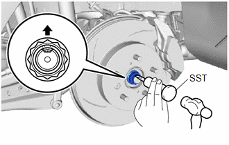
3. REMOVE REAR AXLE SHAFT NUT
| (a) Using SST and a hammer, release the staked part of the rear axle shaft nut. SST: 09930-00010 NOTICE: Loosen the staked part of the rear axle shaft nut completely, otherwise the threads of the rear drive shaft assembly may be damaged. |
|
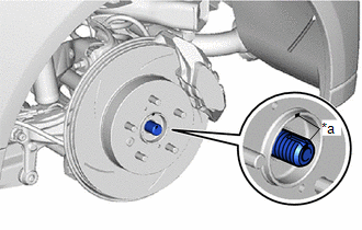
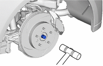
(b) Using a 30 mm deep socket wrench, remove the rear axle shaft nut while applying the brakes.
4. SEPARATE REAR SPEED SENSOR
Click here

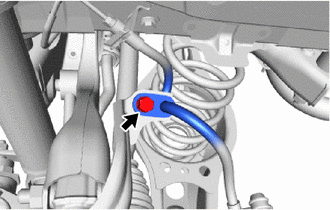
5. SEPARATE REAR FLEXIBLE HOSE
| (a) Remove the bolt and separate the rear flexible hose from the flexible hose bracket. |
|
6. REMOVE REAR STABILIZER LINK ASSEMBLY
Click here

7. REMOVE REAR COIL SPRING
Click here

8. REMOVE REAR LOWER COIL SPRING INSULATOR
Click here

9. REMOVE REAR NO. 2 SUSPENSION ARM ASSEMBLY
Click here

10. REMOVE REAR NO. 1 SUSPENSION ARM ASSEMBLY
Click here

11. SEPARATE REAR UPPER CONTROL ARM ASSEMBLY
| (a) Remove the bolt and nut, and separate the rear upper control arm assembly from the rear axle carrier sub-assembly. NOTICE: Loosen the bolt with the nut secured. |
|

12. REMOVE REAR DRIVE SHAFT ASSEMBLY
| (a) Put matchmarks on the rear drive shaft assembly and the rear axle hub and bearing assembly. |
|
| (b) Using a plastic hammer, separate the rear drive shaft assembly from the rear axle hub and bearing assembly. NOTICE:
HINT: If it is difficult to separate the rear drive shaft assembly rear axle hub and bearing assembly, tap the end of the rear drive shaft assembly using a brass bar and a hammer. |
|
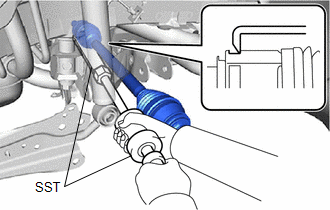
| (c) Using SST, remove the rear drive shaft assembly from the rear differential carrier assembly. SST: 09520-01010 SST: 09520-20010 09521-02010 09521-02040 09521-02060 NOTICE:
|
|
13. REMOVE REAR DRIVE SHAFT INBOARD JOINT SHAFT SNAP RING
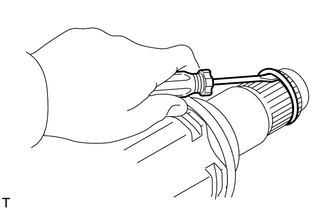
(a) Using a screwdriver, remove the rear drive shaft inboard joint shaft snap ring.
 Components
COMPONENTS ILLUSTRATION
*1 REAR AXLE SHAFT NUT *2 REAR SPEED SENSOR *3 REAR FLEXIBLE HOSE *4 CAP *5 REAR STABILIZER LINK ASSEMBLY *6 REAR STABILIZER BAR *7 REAR COIL SPRING *8 REAR LOWER COIL SPRING INSULATOR *9 REAR NO...
 Disassembly
DISASSEMBLY CAUTION / NOTICE / HINT NOTICE:
When using a vise, place aluminum plates between the part and vise.
When using a vise, do not overtighten it...
Other information:
Toyota Yaris XP210 (2020-2026) Reapir and Service Manual: Crankshaft Position Sensor "A" No Signal (sub) (P033500)
DESCRIPTION Refer to DTC P033511. Click here DTC No. Detection Item DTC Detection Condition Trouble Area MIL Note P033500 Crankshaft Position Sensor "A" No Signal (sub) No crankshaft position sensor signal to the sub ECM while engine running ECM Comes on SAE: P0335 MONITOR DESCRIPTION While the engine is running, when the NE signal is not input to the sub CPU even though the NE signal is input to the main CPU, the ECM judges that a malfunction has occurred in an internal ECM circuit, and illuminates the MIL and stores a DTC...
Toyota Yaris XP210 (2020-2026) Owner's Manual: Cruise Control
With cruise control, you can set and automatically maintain any speed of more than about 16 mph (25 km/h). WARNING Do not use the cruise control under the following conditions Using the cruise control under the following conditions is dangerous and could result in loss of vehicle control...
Categories
- Manuals Home
- Toyota Yaris Owners Manual
- Toyota Yaris Service Manual
- Diagnostic Trouble Code Chart
- Key Battery Replacement
- To Set Speed
- New on site
- Most important about car
Refueling
Before refueling, close all the doors, windows, and the liftgate/trunk lid, and switch the ignition OFF.
To open the fuel-filler lid, pull the remote fuel-filler lid release.
