Toyota Yaris: Smart Key System (for Entry Function) / Driver Side Door Entry Lock Function does not Operate
DESCRIPTION
If the entry lock function does not operate for the driver door only, but the entry unlock function operates, the request code is being transmitted properly from the driver door. In this case, there may be a problem related to the lock sensor (connection between the certification ECU (smart key ECU assembly) and front door outside handle assembly LH).
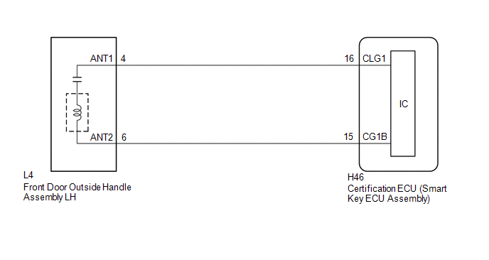
WIRING DIAGRAM
CAUTION / NOTICE / HINT
NOTICE:
- When using the GTS with the ignition switch off, connect the GTS to the DLC3 and turn a courtesy light switch on and off at intervals of 1.5 seconds or less until communication between the GTS and the vehicle begins. Then select the vehicle type under manual mode and enter the following menus: Body Electrical / Smart Key. While using the GTS, periodically turn a courtesy light switch on and off at intervals of 1.5 seconds or less to maintain communication between the GTS and the vehicle.
-
The smart key system (for Entry Function) uses the CAN communication system. Inspect the communication function by following How to Proceed with Troubleshooting. Troubleshoot the smart key system (for Entry Function) after confirming that the communication systems are functioning properly.
Click here

-
Before replacing the certification ECU (smart key ECU assembly), refer to Precaution.
Click here

- After repair, confirm that no DTCs are output.
- Check that there are no electrical key transmitter sub-assemblies in the vehicle.
PROCEDURE
| 1. | CHECK POWER DOOR LOCK CONTROL SYSTEM |
(a) When the door control switch on the multiplex network master switch assembly is operated, check that the doors unlock and lock according to the switch operation.
Click here

OK:
Door locks operate normally.
| NG |
 | GO TO POWER DOOR LOCK CONTROL SYSTEM |
|

| 2. | CHECK ENTRY OPERATION |
(a) Check that the entry lock function.
| (1) Turn the ignition switch off. |
|
(2) Open and close the driver door.
(3) Hold the electrical key transmitter sub-assembly at the same height as the door outside handle assembly LH and approximately 0.3 m (0.984 ft.) from the driver door.
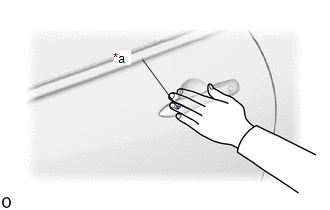
(4) Touch the lock sensor of the front door outside handle assembly LH (groove on the front door outside handle) with 2 or more fingers for 2 seconds or more.
HINT:
- If the door does not lock even when touching the lock sensor for 2 seconds or more, touch it with your palm.
- When checking the operation of the lock sensor again, make sure to perform the procedure from step (1).
- When checking the operation of the entry lock function several times, it can be operated up to 2 times consecutively. To operate the function 3 times or more consecutively, the doors need to be unlocked once. However, this is only for the entry lock function, other door lock operations, such as a wireless door lock operation can be performed consecutively.
| Result | Proceed to |
|---|---|
| Entry function does not operate normally | A |
| Entry function operates normally | B |
| B |
 | GO TO CHECK FOR INTERMITTENT PROBLEMS (OPERATION HISTORY) |
|

| 3. | READ VALUE USING GTS (DRIVER SIDE LOCK SENSOR) |
| (a) Open and close the driver door. |
|

(b) Hold the electrical key transmitter sub-assembly at the same height as the door outside handle assembly LH and approximately 0.3 m (0.984 ft.) from the driver door.
(c) Read the Data List according to the display on the GTS.
(d) Touch the lock sensor of the front door outside handle assembly LH (groove on the front door outside handle) with 2 or more fingers for 2 seconds or more.
HINT:
- If the door does not lock even when touching the lock sensor for 2 seconds or more, touch it with your palm.
- When checking the operation of the lock sensor again, make sure to perform the procedure from step (a).
- When checking the operation of the entry lock function several times, it can be operated up to 2 times consecutively. To operate the function 3 times or more consecutively, the doors need to be unlocked once. However, this is only for the entry lock function, other door lock operations, such as a wireless door lock operation can be performed consecutively.
| Tester Display | Measurement Item | Range | Normal Condition | Diagnostic Note |
|---|---|---|---|---|
| Driver Side Lock Sensor | Driver door touch sensor (lock sensor) | OFF or ON | OFF: Driver door touch sensor (lock sensor) not touched ON: Driver door touch sensor (lock sensor) touched |
|
| Tester Display |
|---|
| Driver Side Lock Sensor |
OK:
The GTS display changes correctly in response to the operation of the front door outside handle assembly LH.
| OK |
 | REPLACE CERTIFICATION ECU (SMART KEY ECU ASSEMBLY) |
|

| 4. | CHECK HARNESS AND CONNECTOR (CERTIFICATION ECU (SMART KEY ECU ASSEMBLY) - FRONT DOOR OUTSIDE HANDLE ASSEMBLY LH) |
(a) Disconnect the H46 certification ECU (smart key ECU assembly) connector.
(b) Disconnect the L4 front door outside handle assembly LH connector.
(c) Measure the resistance according to the value(s) in the table below.
Standard Resistance:
| Tester Connection | Condition | Specified Condition |
|---|---|---|
| H46-16 (CLG1) - L4-4 (ANT1) | Always | Below 1 Ω |
| H46-15 (CG1B) - L4-6 (ANT2) | Always | Below 1 Ω |
| H46-16 (CLG1) or L4-4 (ANT1) - Other terminals and body ground | Always | 10 kΩ or higher |
| H46-15 (CG1B) or L4-6 (ANT2) - Other terminals and body ground | Always | 10 kΩ or higher |
(d) Reconnect the L4 front door outside handle assembly LH connector.
(e) Reconnect the H46 certification ECU (smart key ECU assembly) connector.
| NG |
 | REPAIR OR REPLACE HARNESS OR CONNECTOR |
|

| 5. | READ VALUE USING GTS (DRIVER SIDE LOCK SENSOR) |
| (a) Open and close the driver door. |
|

(b) Hold the electrical key transmitter sub-assembly at the same height as the door outside handle assembly LH and approximately 0.3 m (0.984 ft.) from the driver door.
(c) Read the Data List according to the display on the GTS.
(d) Touch the lock sensor of the front door outside handle assembly LH (groove on the front door outside handle) with 2 or more fingers for 2 seconds or more.
HINT:
- If the door does not lock even when touching the lock sensor for 2 seconds or more, touch it with your palm.
- When checking the operation of the lock sensor again, make sure to perform the procedure from step (a).
- When checking the operation of the entry lock function several times, it can be operated up to 2 times consecutively. To operate the function 3 times or more consecutively, the doors need to be unlocked once. However, this is only for the entry lock function, other door lock operations, such as a wireless door lock operation can be performed consecutively.
| Tester Display | Measurement Item | Range | Normal Condition | Diagnostic Note |
|---|---|---|---|---|
| Driver Side Lock Sensor | Driver door touch sensor (lock sensor) | OFF or ON | OFF: Driver door touch sensor (lock sensor) not touched ON: Driver door touch sensor (lock sensor) touched |
|
| Tester Display |
|---|
| Driver Side Lock Sensor |
OK:
The GTS display changes correctly in response to the operation of the front door outside handle assembly LH.
| OK |
 | END (CONNECTOR WAS NOT CONNECTED SECURELY) |
| NG |
 | REPLACE FRONT DOOR OUTSIDE HANDLE ASSEMBLY LH |
 Front Passenger Side Door Entry Lock and Unlock Functions do not Operate
DESCRIPTION If the entry lock and unlock functions do not operate for the front passenger door only, the request code may not be being transmitted from the front passenger door or the front door outside handle assembly RH (touch sensor) may be malfunctioning...
 Front Passenger Side Door Entry Lock Function does not Operate
DESCRIPTION If the entry lock function does not operate for the front passenger door only, but the entry unlock function operates, the request code is being transmitted properly from the for passenger door...
Other information:
Toyota Yaris XP210 (2020-2026) Reapir and Service Manual: How To Proceed With Troubleshooting
CAUTION / NOTICE / HINT HINT: Use the following procedure to troubleshoot the lighting system. *: Use the GTS. PROCEDURE 1. VEHICLE BROUGHT TO WORKSHOP NEXT 2. CUSTOMER PROBLEM ANALYSIS AND SYMPTOM CHECK HINT: In troubleshooting, confirm that the problem symptoms have been accurately identified...
Toyota Yaris XP210 (2020-2026) Owner's Manual: Fuel Consumption Display
Information regarding the fuel economy is displayed. Displays the fuel economy for the past 60 minutes. Displays the fuel economy every minute for the past 1 to 10 minutes. Displays the fuel economy every 10 minutes for the past 10 to 60 minutes...
Categories
- Manuals Home
- Toyota Yaris Owners Manual
- Toyota Yaris Service Manual
- Immobilizer System
- Removal
- Power Integration No.1 System Missing Message (B235287,B235587,B235787-B235987)
- New on site
- Most important about car
Refueling
Before refueling, close all the doors, windows, and the liftgate/trunk lid, and switch the ignition OFF.
To open the fuel-filler lid, pull the remote fuel-filler lid release.
