Toyota Yaris: Sfi System / Vehicle Speed Sensor "A" No Signal (P050031)
DESCRIPTION
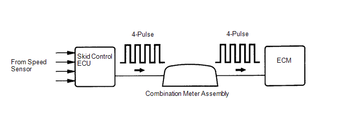
Vehicles, which are equipped with ABS (Anti-lock Brake System), detect the vehicle speed using the skid control ECU (brake actuator assembly) and speed sensor. The speed sensor monitors the wheel rotation speed and sends a signal to the skid control ECU. The skid control ECU converts the wheel speed signal into a 4-pulse signal and transmits it to the ECM via the combination meter assembly. The ECM determines the vehicle speed based on the frequency of the pulse signal.
HINT:
- Various systems use the vehicle speed signal distributed from the combination meter assembly. Check all the components possibly related to speed signal.
-
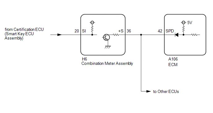
A voltage of 12 V or 5 V is output from each ECU and then input to the combination meter assembly.
The signal is changed to a pulse signal at the transistor in the combination meter assembly. Each ECU controls the respective system based on the pulse signal.
- If a short occurs in any of the ECUs or in the wire harness connected to an ECU, all systems using the speed signal will not operate normally.
| DTC No. | Detection Item | DTC Detection Condition | Trouble Area | MIL | Note |
|---|---|---|---|---|---|
| P050031 | Vehicle Speed Sensor "A" No Signal | While vehicle being driven, no vehicle speed sensor signal transmitted to ECM (2 trip detection logic). |
| Comes on | SAE: P0500 |
MONITOR DESCRIPTION
If there is no speed signal from the combination meter assembly even though the ECM determines that the vehicle is being driven, the ECM interprets this as a malfunction in the speed signal circuit. The ECM then illuminates the MIL and stores this DTC.
MONITOR STRATEGY
| Required Sensors/Components (Main) | Vehicle speed sensor Combination meter assembly Skid control ECU |
| Required Sensors/Components (Related) | Engine coolant temperature sensor Crankshaft position sensor Speed sensor Throttle position sensor Mass air flow meter sub-assembly |
| Frequency of Operation | Continuous |
CONFIRMATION DRIVING PATTERN
- Connect the GTS to the DLC3.
- Turn the ignition switch to ON.
- Turn the GTS on.
- Clear the DTCs (even if no DTCs are stored, perform the clear DTC procedure).
- Turn the ignition switch off and wait for at least 30 seconds.
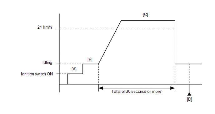
- Turn the ignition switch to ON [A].
- Turn the GTS on.
- Start the engine [B].
-
Drive the vehicle at 24 km/h (15 mph) or more for a total of 30 seconds or more [C].
CAUTION:
When performing the confirmation driving pattern, obey all speed limits and traffic laws.
- Stop the vehicle.
- Enter the following menus: Powertrain / Engine / Trouble Codes [D].
-
Read the pending DTCs.
HINT:
- If a pending DTC is output, the system is malfunctioning.
- If a pending DTC is not output, perform the following procedure.
- Enter the following menus: Powertrain / Engine / Utility / All Readiness.
- Input the DTC: P050031.
-
Check the DTC judgment result.
GTS Display
Description
NORMAL
- DTC judgment completed
- System normal
ABNORMAL
- DTC judgment completed
- System abnormal
INCOMPLETE
- DTC judgment not completed
- Perform driving pattern after confirming DTC enabling conditions
HINT:
- If the judgment result is NORMAL, the system is normal.
- If the judgment result is ABNORMAL, the system has a malfunction.
- If the judgment result is INCOMPLETE, perform steps [C] through [D] again.
WIRING DIAGRAM
CAUTION / NOTICE / HINT
HINT:
Read Freeze Frame Data using the GTS. The ECM records vehicle and driving condition information as Freeze Frame Data the moment a DTC is stored. When troubleshooting, Freeze Frame Data can help determine if the vehicle was moving or stationary, if the engine was warmed up or not, if the air fuel ratio was lean or rich, and other data from the time the malfunction occurred.
PROCEDURE
| 1. | READ VALUE USING GTS (VEHICLE SPEED) |
(a) Enter the following menus.
Powertrain > Engine > Data List| Tester Display |
|---|
| Vehicle Speed |
(b) Drive the vehicle.
(c) Read the value displayed on the GTS.
| Result | Proceed to |
|---|---|
| Values displayed on GTS and speedometer display not equal | A |
| Values displayed on GTS and speedometer display equal | B |
| B |
 | CHECK FOR INTERMITTENT PROBLEMS |
|

| 2. | CHECK HARNESS AND CONNECTOR (COMBINATION METER ASSEMBLY - ECM) |
(a) Disconnect the combination meter assembly connector.
(b) Disconnect the ECM connector.
(c) Measure the resistance according to the value(s) in the table below.
Standard Resistance:
| Tester Connection | Condition | Specified Condition |
|---|---|---|
| H6-36(+S) - A106-42(SPD) | Always | Below 1 Ω |
| NG |
 | REPAIR OR REPLACE HARNESS OR CONNECTOR |
|

| 3. | CHECK COMBINATION METER SYSTEM |
(a) Check the circuits that send vehicle speed signals to this system in the combination meter system.
Click here

|

| 4. | CLEAR DTC |
(a) Clear the DTCs.
Powertrain > Engine > Clear DTCs(b) Turn the ignition switch off and wait for at least 30 seconds.
|

| 5. | CONFIRM WHETHER MALFUNCTION HAS BEEN SUCCESSFULLY REPAIRED |
(a) Drive the vehicle in accordance with the driving pattern described in Confirmation Driving Pattern.
(b) Read the DTCs.
Powertrain > Engine > Trouble CodesHINT:
If no DTCs (no pending DTCs) are output to the GTS, the repair has been successfully completed.
| NEXT |
 | END |
 Evaporative Emission System Purge Control Valve "A" Circuit Open (P044313)
DESCRIPTION To reduce hydrocarbon (HC) emissions, evaporated fuel from the fuel tank is routed through a charcoal canister to the intake manifold for combustion in the cylinders...
 Brake Switch "A"/"B" Signal Cross Coupled (P05042B)
DESCRIPTION The stop light switch assembly is a duplex system that transmits two signals: STP and ST1-. These two signals are used by the ECM to monitor whether or not the brake system is working properly...
Other information:
Toyota Yaris XP210 (2020-2026) Reapir and Service Manual: Rough Idling
DESCRIPTION Problem Symptom Suspected Area Trouble Area Engine speed fluctuation due to abnormal combustion Idle speed too low or high Strong engine vibration due to above symptoms Ignition malfunction Deviation in air fuel ratio (Excessive or insufficient intake air volume or fuel supply) Insufficient compression Changes in load from another system Ignition system Spark plug Ignition coil assembly Fuel system Direct fuel injector assembly Port fuel injector assembly Fuel pump assembly (for high pressure side) Fuel pump (for low pressure side) Fuel pump control circuit Fuel line Purge VSV system Fuel quality (existence of foreign matter, degradation) Intake and exhaust systems Mass air flow meter sub-assembly Intake system (Air leaks or deposit accumulation) Throttle body with motor assembly Air fuel ratio sensor (sensor 1) Air fuel ratio sensor (sensor 2) Cam timing oil control solenoid assembly Variable Valve Timing system (VVT system) Other control systems ECM Wire harness or connector Knock control sensor Engine coolant temperature sensor Engine Water control valve Engine assembly Engine mount High load from another system Air conditioning system Power steering system Electrical load signal system SYMPTOM AND CAUSE OF SYSTEM MALFUNCTION HINT: The following are descriptions of the characteristics of each system malfunction...
Toyota Yaris XP210 (2020-2026) Reapir and Service Manual: Removal
REMOVAL PROCEDURE 1. REMOVE CENTER LOWER INSTRUMENT COVER Click here 2. REMOVE LOWER INSTRUMENT PANEL FINISH PANEL Click here 3. REMOVE SWITCH HOLE BASE SUB-ASSEMBLY Click here 4. REMOVE SHIFT LEVER KNOB SUB-ASSEMBLY Click here 5. REMOVE CONSOLE BOX ASSEMBLY Click here 6...
Categories
- Manuals Home
- Toyota Yaris Owners Manual
- Toyota Yaris Service Manual
- Power Integration No.1 System Missing Message (B235287,B235587,B235787-B235987)
- Engine & Hybrid System
- Auto Lock/Unlock Function
- New on site
- Most important about car
Break-In Period
No special break-in is necessary, but a few precautions in the first 600 miles (1,000 km) may add to the performance, economy, and life of the vehicle.
Do not race the engine. Do not maintain one constant speed, either slow or fast, for a long period of time. Do not drive constantly at full-throttle or high engine rpm for extended periods of time. Avoid unnecessary hard stops. Avoid full-throttle starts.